Original Link: https://www.anandtech.com/show/6541/the-state-of-qualcomms-modems-wtr1605-and-mdm9x25
The State of Qualcomm's Modems - WTR1605 and MDM9x25
by Brian Klug on January 4, 2013 9:48 PM ESTA little over a month ago, Qualcomm flew me out to San Diego to talk all about cellular modem, specifically their baseband lineup, testing, and later their RF and transceiver in what would become their largest RF disclosure ever. In the past few years, we’ve made considerable headway getting SoC vendors to disclose details on the CPU and GPU side of their products, and mobile enthusiasts now are starting to become increasingly cognizant of the SoC inside devices, and in turn the blocks inside that SoC. In a short term the industry as a whole went from smartphones largely being impenetrable black boxes to devices with understandable platforms inside. The days of an OEM not disclosing what SoC was inside a device at all are largely behind us, and for the most part vendors are open to discussing what’s really inside most of their silicon quite publicly.
The last real remaining black box from my point of view is the cellular connectivity side of things. So much of what drives smartphone design and OEM choice lately is, unsurprisingly, how the device gets connected to the cellular network, and baseband remains largely a black box by design for a number of reasons. The focus of this article is specifically about Qualcomm’s newest transceiver, WTR1605L, and some more details about MDM9x25 and MDM9x15.
Cellular Radio Architecture at a High Level
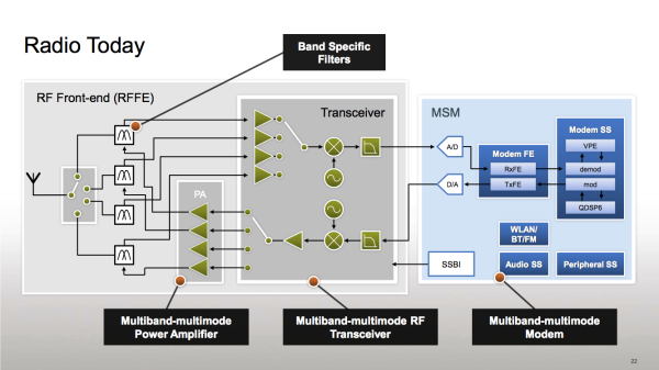
Before we talk about what’s new, it bears going over cellular architecture at a high level to make things easier to understand, which is something we’ve admittedly never really done. Connecting a smartphone to a cellular network is a complicated goal, but like anything there are really only a few high level functional blocks to worry about. Understanding this architecture at a high level allows one to understand how OEMs build devices with support for multiple bands and modes, and why some designs are limited to one combination of features or another. We talk a lot about cellular baseband, but really this is just one part of the entire cellular chain on a handset. There’s of course an antenna array, and after that a switch or switches, filters for the appropriate bands, and then for receive there’s the transceiver, and finally baseband. Transmit takes much the same path, but instead of some low noise amplifiers in the transceiver, there are appropriate external power amplifiers to boost output signal to a given level for each specific transmit band.
So what role do each of those play? Antenna is pretty self explanatory — handsets have anywhere from one to four cellular antennas, each tuned for a specific band or purpose. Devices with LTE must include at least two receive chains since receive diversity is mandatory, and almost all LTE devices use a 2x1 configuration with two receive chains (in order to do 2x2 MIMO to the base station) and one transmit chain. The transmit chain usually shares the primary receive antenna, thus we see at a minimum two antennas for a normal LTE handset. Simultaneous transmission modes such as SVLTE (Simultaneous Voice and LTE) and SVDO (Simultaneous Voice and EVDO) thus far necessitate an additional dedicated transmit chain as well, bringing the total to three. Occasionally an OEM will also include an additional diversity antenna tailored for a specific band, bringing it to four. The geometry of an antenna fundamentally defines its gain and other characteristics for a given frequency band (wavelength), and is a huge part of the industrial design and form factor tradeoff for handset design. Often these are competing factors in a handset.
Switches are another fundamental part of almost every design, and are used for changing paths between the antenna and transceiver, either through the appropriate power amplifier or appropriate antenna. In TDD (Time Division Duplexing) systems, the switch is also fundamentally important since it is responsible for quickly switching between transmit and receive chains since transmit and receive are on the same band. In FDD (Frequency Division Duplexing) systems, there’s the need for a duplexer which isolates the receive and transmit bands from interfering each other.
Filters (think band pass) reject everything outside a given band and isolate a specific frequency range appropriate to whatever band class is being used. The performance of these filters is a continual subject of both scrutiny and improvement, and defines the size of guard bands in-between carriers, minimize harmonics from causing interference in other bands, and so on. In LTE for example a big concern is band 12/17 and 13 coexistence on the same band, something possible only with the latest filters.
Next in the chain is the transceiver, whose role is ultimately to downconvert the incoming signal on the receive side to I/Q data which then gets sent into the baseband (hence the name baseband, this is the complex representation of the RF signal), and on the transmit side synthesize and mix I/Q data from the baseband into RF signal for transmission. Put another way, transceiver converts from RF to baseband. There are usually a number of ports on the transceiver arranged into an arrangement of high and low bands which are tuned to work best at a given set of frequencies. If you’re not familiar with what I’m referring to when I bring up I/Q data, I encourage you to check out my Veer 4G article where I explain QAM and modulation and the I/Q plot.
Finally we have the baseband, which effectively functions as the controller for power amplifiers, switches, and transceiver and handles all the demodulation of received I/Q data and modulation for transmission. In addition the baseband worries about the layers above physical required to get the phone online, for example signaling required for the particular air interface. I’ve seen people refer to this as digital baseband, baseband processor, and modem interchangeably, it’s the same part they’re referring to. It’s this baseband which, at the end of the day, converts that RF signal into bits for the AP (Application Processor) to deal with. For cellular basebands, this is also where things like voice encoding and increasingly GNSS (Global Navigation Satellite System) reside, as these tasks just end up being yet another process running on what usually boils down to an ARM CPU and some DSP running a realtime OS of some kind. At some level the modem really just is another AP running a different workload with very specific DSP onboard.
In the case of a lot of Qualcomm SoCs (MSMs), the baseband processor sits alongside AP onboard the SoC, but the same design may also be reused and exist in a discrete part as well. For example the baseband IP block onboard MSM8960 is shared with MDM9x15, and there will be another SoC which is analogous with MDM9x25.
The transceiver and baseband combination fundamentally define the air interfaces that a device will or can support, and the number and configuration of bands as well. OEMs can always add support for more bands with a switch outside, but of course switches have their own insertion losses and thus affect link budget.
So that’s a very high level overview of cellular radios today, a subject whose complexity is further increasing with the addition of more and more radios, modes, and bands for even more connectivity on mobile devices. It’s the combination of all of these components that contribute to a given device being able to connect to, say, LTE versus just a flavor of WCDMA, or one band versus another.
Qualcomm's New Flagship Transceiver - WTR1605
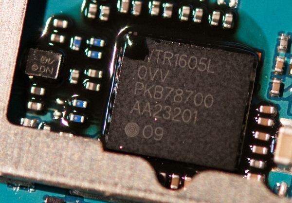
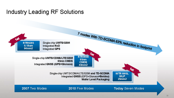
The big new news information disclosure from Qualcomm relates to the capabilities and specifications of their new flagship transceiver, WTR1605 and how it compares to the previous generation, RTR8600. There are a number of new additions, but at a high level it boils down to different packaging (wafer level instead of plastic), inclusion of support for more primary receive bands (7 instead of 5), and support for one more GNSS constellation (the addition of the Chinese system, Beidou) over the previous generation. WTR1605 comes in two flavors, with WTR1605L including L for LTE. The first character in the name indicates package type, which is now wafer-level (hence the W) instead of a plastic, which Qualcomm tells me it can now inspect and test just as effectively as the plastic packaged previous generations. This allows the overall size of WTR1605L to be smaller in spite of it still being fabricated on a 65nm RF CMOS process (there was some previous documentation which suggested that WTR1605L was 28nm RF CMOS, this is not the case).
As a deviation, I also enquired whether we’ll see transceiver ever make it back inside the baseband package, similar to how MDM6x00 was a combination of baseband and transceiver in one single package. Other baseband manufacturers also have sold combination baseband and transceiver parts before, for example LG’s L2000 LTE chipset is a combo part. I originally suspected that this move back to discrete was done to decouple the two roadmaps (since we’ve seen MDM9x15 originally ship with RTR8600 and only now have seen phones with WTR1605L inside), but it turns out the reason is both the multiplicative effect of yields when combining multiple devices into one package (essentially cost), and that the overall system size is smaller with discrete wafer level packages for transceiver.
| RF Ports Comparison | |||||||
|
RTR6285 (3rd Gen) |
RTR8600 (4th Gen) |
WTR1605(L) (5th Gen) |
|||||
| Package Size, Type, Geometry |
64 mm^2, Plastic 0.18µm RF CMOS |
48 mm^2, Plastic 65nm RF CMOS |
25 mm^2, Wafer-Level 65nm RF CMOS |
||||
| Air Interfaces | UMTS/GSM | UMTS/GSM/CDMA/LTE | UMTS/GSM/CDMA/LTE-A/TD-SDCDMA | ||||
| GNSS Support | GPS | GPS, GLONASS | GPS, GLONASS, Beidou | ||||
| Primary Rx | HB (2.1 - 2.6 GHz) | 0 | 1 | 1 | |||
| MB (1.5 - 2.1 GHz) | 2 | 2 | 3 | ||||
| LB (700 - 900 MHz) | 2 | 2 | 3 | ||||
| Diversity Rx / MIMO | HB (2.1 - 2.6 GHz) | 0 | 1 | 1 | |||
| MB (1.5 - 2.1 GHz) | 2 | 2 | 1 | ||||
| LB (700 - 900 MHz) | 1 | 2 | 2 | ||||
| Transmit | HB (2.3 - 2.6 GHz) | 0 | 1 | 1 | |||
| MB (1.5 - 2.1 GHz) | 3 | 4 | 4 | ||||
| LB (700 - 900 MHz) | 2 | 4 | 4 | ||||
| Total Rx Ports | 7 | 10 | 11 | ||||
| Total Tx Ports | 5 | 9 | 9 | ||||
The biggest change with WTR1605 is the inclusion of two more primary receive (Rx) ports over the previous generation, RTR8600. Qualcomm uses a low band, mid band, and high band convention for its ports, which is a common industry practice. These ports are tuned to work over the given band of frequencies, and are all created equal in terms of capabilities, and all wide enough to all do 20 MHz LTE or more. The addition of one more low band and mid band primary receive port on WTR1605 enables a number of configurations for handsets that weren’t possible previously without including a switch outside and incurring some loss. Probably the best example is delivering a device with both Band 17/12 and Band 13, 700 MHz North American coexisting on the same handset (Band 13 is Verizon LTE in the USA, Band 17 is AT&T LTE), and for the extra mid band port, Band 3 (1800 MHz) LTE. More ports means more bands without using up a lot more area on the PCB, and the number of LTE bands is continuing to increase.
I was a bit intrigued by the loss of a mid band diversity port from RTR8600 to WTR1605 and what implications this would have on LTE operation where receive diversity is mandatory for all UE categories, and because this “diversity” port is really the second receive chain mandatory for UE categories 2 and higher. The answer is that the mid band diversity port can accommodate 6 dB of difference from the primary port and the receiver can still do its diversity combining (MRC or so on) and get appreciable gains out. Thus adding a switch in front (around 0.2–0.5 dB of loss) doesn’t incur so much as to be a real problem — and the tradeoff yields one more mid band primary port.
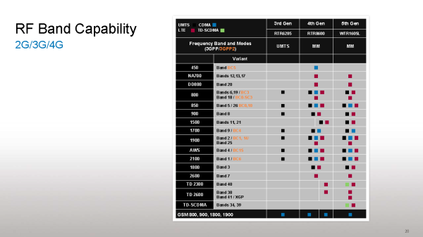
The final addition is TD-SCDMA compatibility which is very important for the Chinese market, specifically China Mobile. Previous to this disclosure, I was unaware that only WTR1605 in conjunction with appropriate baseband is capable of working with TD-SCDMA. This second chart lists all the currently disclosed bands that all three generations are specified as supported, and indicates that only the latest generation includes TD-SCDMA support. The fact that WTR1605 is necessary for TD-SCDMA has implications for a number of handset designs which shipped with MDM9x15 and included RTR8600 for time to market reasons but by an OEM with clear designs on shipping TD-SCDMA enabled SKUs.
I expect that WTR1605 will stick around and be paired with MDM9x25 in the future in addition to MDM9x15 where we’ve seen it first emerge. Clearly Qualcomm feels its synthesizers onboard WTR1605 are up to the task for the number of inter-band and intra-band carrier aggregation combinations being posed in 3GPP Release 10.
Overall WTR1605 is a step in the right direction with more primary receive ports over the previous generation. More ports means a step closer toward the holy grail of a single SKU with all the necessary LTE bands for multiple regions. Unfortunately even with 7 total ports for bands, LTE roaming and shipping a single SKU still remains a difficult to impossible prospect for even the most aggressive OEMs. Obviously the long term goal is to be able to accommodate more ports, the challenge is doing so without driving up cost or size dramatically.
MDM9x25
After the transceiver (and its downconversion from RF to baseband for receive and upconversion from baseband to RF for transmit) comes the digital baseband. In the case of Qualcomm’s architecture, there are two Rx output pairs for I/Q data, and one transmit port. This shouldn’t be surprising since again only two receive ports are needed at maximum to do the 2x2 MIMO modes for LTE or receive diversity. Even though Release 8 supports up to four layers to be transmitted on the downlink, virtually all handsets and data cards use 2 layers at most at present, and this will be the case with MDM9x25 as well. Going up to four layers will pose interesting challenges for handset design where getting enough sufficient inter-antenna spacing to yield good gains in throughput (and independent streams of data) is already a delicate balancing act. Of course operators will need to deploy 4 antennas per sector as well for 4x4.
We’ve seen the first and second generations of Qualcomm’s LTE basebands, first the MDM9x00 series which was 45nm, and now devices are making it onto the market with MDM9x15 (and its LTE-less sibling MDM8215) series which is 28nm and natively voice enabled. The major improvement between 9x00 and 9x15 was of course lower idle and active power consumption, and a smaller package thanks to the change in process geometry. Additionally, MDM9x15 no longer requires a Qualcomm SoC paired with it to be voice enabled, which opens it up for use in platforms like the iPhone where an OEM has a specific non-Qualcomm SoC it wants to use. This same IP block is again shared with MSM8960 and a few other SoCs. Likewise, in the future MDM9x25 will share an IP block with the MSM8960 successor I alluded to earlier.
| Baseband Comparison | ||||||
| MDM9x00 | MDM9x15 | MDM9x25 | ||||
| Package Size, Type, Geometry |
13x13 mm, Plastic 45nm CMOS |
10x10mm, Plastic 28nm CMOS |
10x10mm(?), Plastic 28nm CMOS |
|||
| LTE |
LTE TDD/LTE Cat. 3 (102 Mbps) |
LTE TDD/FDD Cat. 3 (102 Mbps) |
LTE-A TDD/FDD with Carrier Aggregation, Cat. 4 (150 Mbps) |
|||
| HSPA+ | DC-HSPA+ 42 (64QAM, Dual Carrier) - 3GPP Release 8 | DC-HSPA+ 42 (64QAM, Dual Carrier) - 3GPP Release 9 | DC-HSPA+ 84 (64QAM, Carrier Agg., MIMO) - 3GPP Release 10 | |||
| CDMA | 1x Adv / EVDO Rev A/B | 1x Adv / EVDO Rev A/B | 1x Adv / EVDO Rev A/B | |||
| TD-SCDMA | N | Y | Y | |||
| Voice Enabled (without SoC Fusion) | N | Y | Y | |||
| GNSS | gpsOneGen 8 with GLONASS | gpsOneGen 8A with GLONASS | gpsOneGen 8B with GLONASS | |||
| Onboard AP for optional WiFi AP | ARM Cortex A5 | ARM Cortex A5 | ARM Cortex A5 | |||
Enabling voice and all the legacy fallback modes required for it is a huge task, and Qualcomm believes it has significant leadership by supporting all the combinations of handover and fallback modes required for support of voice services. This includes CSFB (Circuit-Switched Fallback), dual radio (1xRTT alongside LTE), and VoLTE (with and without SRVCC).
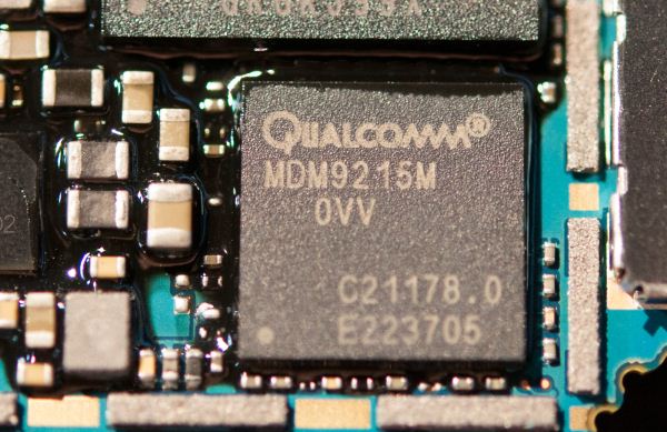
Recently Qualcomm announced that its third generation LTE baseband, MDM9x25 had begun sampling to device makers, and this is a particularly interesting part since it’s Qualcomm’s first LTE UE Category 4 baseband. Just like in the WCDMA release, the 3GPP has UE Categories for LTE which define what capabilities a given device has. Because LTE has variable channel bandwidths, this time around UE category is defined based on the number of resource blocks and spatial streams a device can support. In UE Category 3 this corresponded to 100 Mbps maximum on a 20 MHz downlink channel, in category 4 this is the full 150 Mbps - 100 resource block allocation - for 20 MHz channels.
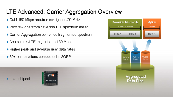
At the same time, 20 MHz of contiguous spectrum is difficult for operators to come across in most regions, thus the 20 MHz FDD channel bandwidth that is supported in LTE isn’t widely used in some major markets where LTE is deployed at present. The mitigation is to allow for carrier aggregation in LTE similar to carrier aggregation for DC-HSPA+ (dual carrier). Currently shipping DC-HSPA+ configurations require carriers to be adjacent to each other in order to be aggregated, and this requires contiguous spectrum (in which case the operator could just run that channel bandwidth of LTE in the first place). What’s new in Release 10 and will be supported on MDM9x25 is inter-band and intra-band aggregation for both WCDMA and LTE. That is, aggregation of LTE carriers that don’t need to be next to each other and instead can be inside the same band (continuous or non continuous), or across multiple bands, for a number of configurations. This allows wireless operators to piece together enough bandwidth from their spectrum holdings across bands to get performance on par with one bigger contiguous carrier, for example 10 MHz FDD + 10 MHz FDD aggregation to emulate 20 MHz FDD performance. Just like in WCDMA, uplink remains unchanged in an FDD scenario, these carriers aren’t aggregated, but most of the time the traffic profile on cellular networks is similarly asymmetric to begin with. I’m told that MDM9x25 is capable of supporting aggregation of even a third WCDMA carrier which is another 3GPP proposed mode.
WCDMA also gets an improvement from the LTE side of things, support for 2x2 MIMO which increases the theoretical maximum bitrate on the downlink to 84 Mbps from 42 Mbps.
MDM9x25 should be an exciting part to keep an eye on. We’re still a ways off from seeing carriers light up LTE Advanced (release 10) features, and similarly still a ways off from seeing MDM9x25 in devices, though it could show up in tablets or be targeted at high end smartphones. As always, understanding some of the players roadmaps helps get a better grasp on what’s in store in the future.
Conclusions
The mobile device industry has come a considerable way in just two years. Previously, getting this kind of open disclosure about RF architecture and ports was largely unheard of. On the modem side, both operators and handset makers have considerable interest in making sure that the baseband is as close to a black box as possible for security reasons (security through obscurity at its finest). The platform architecture of a handset with clear separation between AP and modem as this detached and separate means of getting data, voice, and SMS also inherently fosters a black box approach to the whole cellular connectivity side. There are still more questions to answer and even more areas of the smartphone platform that should make it into daylight and out of from behind walls of NDAs, but this is a great step in the right direction. The ultimate goal for me is to have the equivalent of the transceiver and modem table filled out for some of the popular products from the other major vendors and gain a better understanding of the entire space.
The next topic is just what impact the introduction of WTR1605L and MDM9x25 will have on the space. WTR1605 introduces sorely needed additional ports which can be used for additional LTE bands. The reality of LTE at the moment is that the number of bands being proposed for 3GPP releases is only continuing to increase. Additional primary ports does in turn mean OEMs can choose to include maybe one or two more LTE bands, but roaming on all of the popular bands still is an unsolved problem. We’ve already seen designs including WTR1605 on the market, none of which have really gone above and beyond with more LTE bands. At the same time I expect to see devices with band 12/17 and 13 coexistence start popping up. Of course the TD-SCDMA story is perhaps the most under appreciated aspect, as China Mobile presents a market whose size is almost staggering in scale that everyone wants a piece of.
The reality is that the industry still needs more time for the LTE band landscape to settle down, refarming of existing 2G and 3G spectrum by operators, in addition to even more band support on handsets to enable one SKU solutions.

