
Original Link: https://www.anandtech.com/show/2259
AnandTech Power Supply Test Methodology
by Christoph Katzer on July 12, 2007 12:00 AM EST- Posted in
- Cases/Cooling/PSUs
Danger - High Voltage!

The readers of AnandTech have waited a long time for us to do real power supply reviews. The waiting has come to an end and we hope you will find the results to be worthwhile. In the near future we will begin publishing power supply reviews on a regular basis, with the goal of providing the detailed analysis and benchmarking results our readers have come to expect.
We know the AnandTech audience expects a high level of professionalism, and it took a while to put together the right equipment in order to provide that for PSU testing. To kick things off, we want to talk about each part of the equipment and how it will help us with the reviews. With a proper understanding of the equipment and testing methodology, we hope you will see what will make the AnandTech power supply reviews so special.
Why It is so Difficult to Test Power Supplies
Over the past couple of years few markets in the IT industry have grown as rapidly as the power supply sector. Faster and more powerful CPUs, GPUs, and other components have led to a need for better and more powerful PSUs. A few years ago, most would have laughed at the thought of a desktop PC with a 700W or greater PSU, and yet such designs are becoming increasingly common. Companies are sprouting out of the ground like mushrooms and everybody wants a share of this fast evolving market.
With growing interest in power supplies it is natural that websites will take an interest in reviewing and testing them. However, power supplies are not as easy to test as many other components. For example, unlike a graphics card, CPU, or motherboard it is not enough to simply plug it in and run several of the latest 3D shooters.
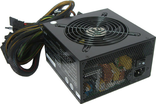
Unfortunately, most published reviews on the internet are done in this manner. The DC outputs are quickly measured separately with a multimeter - or even worse the motherboard's BIOS. The rails seem to be stable, it runs the test system without difficulty, and it is relatively quiet; good enough for a Gold Award! These kinds of reviews do more harm than good to the actual users.
Because of the simple test rigs that are employed, the power supplies are not even close to being fully loaded and thus the DC outputs are generally without problem. It is also difficult or impossible to find flaws in this manner which would otherwise prevent people from buying a dangerous product. A certain PSU might run in system A just fine only to break down from an overload in system B and cause damage to the whole system. In addition to this type of problem, cheaper power supplies lack security features which should have been there for a reason.
The bottom line is, a normal PC is just not enough to fully load a high-end power supply, and therefore it cannot be properly tested and surely not approved by such a configuration.
AnandTech Power Supply Test Methodology
The only way to test a power supply correctly is with special equipment designed for such tests. This starts with programmable loads, which allow the loading of precise amperages on the power supply. Next, a power meter will be needed to measure the exact amount of power used during testing. Power meters can be found in a variety of versions already, ranging from the simple to the complex, and it's good to see that some publications already test with this method.
To test the quality of the DC output we need an oscilloscope as well. This is important since each output has certain ripple and noise levels, and these are different with each power supply - even those from the same manufacturer. The ripple and noise are leftovers from the electric pulse, and every power supply should implement certain measures to reduce the ripple to an acceptable grade. The actual Power Supply Design Guide specifies that each +12V rail should not have any ripple over 120mV and the +3.3V and +5V rails should not have any ripple over ~50mV. Unfortunately we cannot present these tests right away since we are still working on the best methods. We will conduct those measurements soon and include them in the reviews.
It should be quite clear now that we will need some serious equipment to conduct all these tests. To assure our readers of the most professional and accurate reviews on the web, we are building our PSU test lab based on equipment from the renowned company Chroma. With the Chroma test equipment we can make clear and very accurate measurements and load power supplies controlled in ways that are impossible to achieve using only a PC. On the following pages we will introduce our equipment and the ways they will contribute to future power supply reviews.
Chroma Programmable AC Source 61604
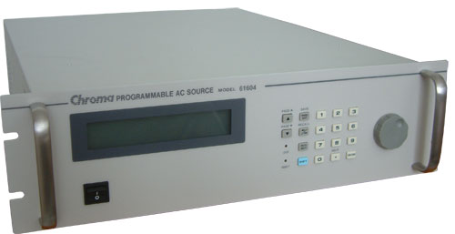
In most parts of the world it is usual to use a grid power of 230VAC with a frequency of 50Hz. In the US, Canada, and parts of South America however the standards are around 117VAC with a frequency of 60Hz (commonly rounded to 120VAC). To provide our readers the maximum range the units can handle, we are testing power supplies with multiple inputs in these different voltage ranges.
The difference in the DC output between 110VAC and 120VAC is marginal, but from 120VAC to 230VAC it's another story. Lower input voltage results in a higher energy usage by the power supply, and higher power usage lowers the efficiency of each power supply. Therefore we will see differences between tests at 115VAC and those at 230VAC. By covering these two different input voltages of 115VAC and 230VAC we will offer a good variety for all our readers and we will provide the only current public tests conducted at both input voltages.
The Chroma model 61604 is capable of providing 0 - 300VAC with a power up to 2000 volt-amperes (VA). The output frequency can be selected between 15Hz and 1000Hz. To simulate a perfect environment we use 50Hz for the test with 230VAC and 60Hz for 115VAC, which is what users generally find at the power grid in various countries.
However, our AC Source actually provides two functions. The first is that it acts as a normal AC Source, allowing us to test with different voltages. Second, it is also a power meter that gives us important data like power usage and power factor.
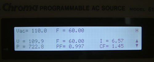
The display shows us several important numbers. The top row contains information regarding the power that we want the device to deliver. The two lower rows display the actual delivered voltage, power consumption from the power grid, frequency, power factor, current and the crest factor. For our tests the most important items are the voltage, frequency, power consumption and power factor. In our reviews we will include a graph which will show the energy loss from the power supply during testing as follows.
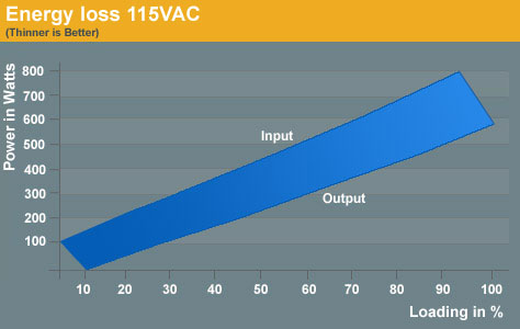
Sample Energy Loss
The upper line marked with Input is the actual power drawn from the power grid. The line below marked with Output is the DC power which is given to the PC. Usually at lower power draws from the system the power loss will be lower as well. This can be seen by the increasing distance between the two lines, which grows steadily with increasing power usage.
By loading a power supply at a specific level, we get both the power input and the power output. Dividing these two units gives the efficiency of each tested power supply. Efficiency has become a modern benchmark for power supplies and many companies build their complete marketing strategy on high efficiency. To make this efficiency readable we will use a graph which shows each step at a specific point of load. To get the best overall impression of a power supply we decided to test in steps of 10% of the actual load each power supply is able to deliver. The load of each rail is calculated in conformity with the Power Supply Design Guide V1.1 released by Intel in March of this year.
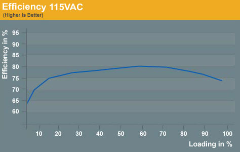
Sample Efficiency
The efficiency is normally displayed in a curve which starts at a low point around 60 to 70%. With increasing loads the curve will usually reach its zenith at 50% to 70% of the maximum load the power supply can handle. This means that at this point the power supply has its best efficiency and ideally it should spend most of its time running in this area. High loads push the power supply beyond this point to where the curve is normally heading down again.
The important thing to take away from this is that it's not easy to buy a perfect power supply for the home PC and a little bit of calculation needs to be done. Remember that the power supply should not run at lower or higher loads most of the time. The former happens when a user buys a power supply that provides more potential power than they need, while the latter occurs when users purchase power supplies that meet their minimum requirements. This is information that many marketing departments aren't interested in disseminating, however, and some companies are advertising power supplies rated at more than 1000W - something which few if any PCs will need at the moment.
Chroma Programmable DC Loads 6314
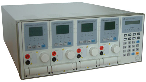
Our test equipment contains two Chroma programmable DC Loads which enable us to test power supplies with an output of up to 1500W. The biggest advantage of the Chroma DC Loads is simply the high precision it provides. It can measure differences as small as 0.001V and 0.0001Amp which will provide us with best-in-class results.
The Chroma programmable load is the heart of our equipment and controls the functions of the power supply. With it we can see the delivered voltage in response to the specific amount of load we are placing on each rail. In addition we will test security features like Over Current Protection (OCP), short circuit, and Over Power Protection (OPP).
A very important aspect in testing a power supply correctly is to put the right load on each rail. Stating that a 10% load is put on the power supply says nothing about the distribution of the load on each rail. For example, this 10% could be 80% load on the +12V1, 5% on +12V2 and +12V3, and 3% on +12V4; the rest would be on the other rails. In other words, simply giving a single all-encompassing load rating means that the load can be put on each rail differently, as long as the total load is always 10%. This is not a correct test according to the Intel Design Guide.
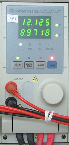
The guide clearly states how the percentages of loads need to be distributed on each rail, and we are working strictly according to this specification. It is not unusual to get an odd looking number since our calculations are strictly mathematical. One of these numbers can be seen in the above picture which shows a single load for the +12V3 rail. We are loading it at that moment with 8.9718 Amps which is the most accurate testing available in the market today. To make the data more accessible for our readers we will be rounding each result to the nearest hundredth, but that is still more accurate than what we see elsewhere.
Temperature
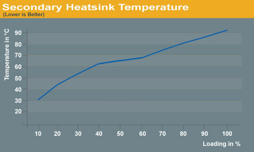
The ambient temperature around the power supply will constantly grow with the time of the test. It will be placed in the same set of conditions it will experience in a real system, where the temperature rises over time. We will start at a room temperature of 77°F (25°C) and constantly measure the exhaust temperature of the power supply and the installed heatsinks inside the PSU. This will tell us how well the power supply can dissipate the produced heat.
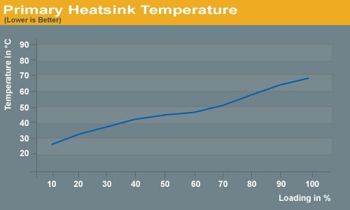
Sample Heatsink Temperature
Sample Heatsink Temperature
It is especially true that as the ambient temperature increases it becomes more difficult for the components of the power supply to deliver the rated specifications. A dropping DC voltage is one potential side effect of this. With increasing heat the lifespan of the PSU and its components will drop tremendously as well. When the power supply is working on our test stand for several hours the heat around it will increase up to 122°F (50°C). At that point it will be running at full load under the most strenuous circumstances possible.
We expect many candidates to fail our full load testing since normal power supplies are all rated just at room temperature of 77°F (25°C). We know we will put power supplies in a very difficult position, but those which pass will be truly worth buying. After all, what's the point of spending a lot of money on a high quality power supply if it can't handle rigorous test scenarios?
Fan Speed and Resulting Sound Pressure Level (SPL)
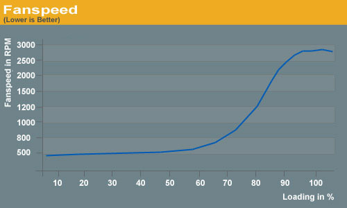
The fan speed and the actual temperature of the heatsinks are completely dependent on each other. If the fan(s) turn slowly the heat inside of the power supply will increase as there will be a lack of heat dissipation from the heatsinks. However, the sound pressure level will drop. Conversely, if the fan speed increases the temperatures get better inside the power supply, because the airflow helps to dissipate the heat. The difficulty comes in balancing the desire for lower temperatures with a competing desire for lower noise levels.
Some companies use slower rotating fans in their power supplies to promote quiet/silent products; unfortunately, they don't mention anything about heat levels that can increase tremendously. The fan of the power supply is not only there to cool down the unit itself but also to help exhaust air from the PC. If you have a very slow rotating fan installed the heat of the system will increase, which increases the heat in the power supply as well. The result is a generally hotter system - hotter CPUs, GPUs, hard drives, memory, etc. - and a very sweaty power supply with drooping DC voltages. This, incidentally, is one of the advantages OEM PCs have over their DIY siblings: the OEM is in control of all aspects of the system, and thus is able to determine an optimal configuration of fans, PSU, etc. The best custom-built PCs should take a similar approach, and simply looking for silence without regards to temperatures can lead to unwanted results.
Companies that promote silent power supplies need to have a very good architecture for the printed circuit board and very high-quality components on it. If they skimp in either area, the components are certain to fail at some point. A good indication of a PSU that generates less heat is the stated efficiency. The more efficient a power supply is working, the less heat will need to be dissipated through the coolers. A few years ago such high-quality designs were uncommon at best but companies wanted to have silent power supplies. The result was that most of the units failed after a short time because of overheating.
The art each company needs to master is running the fan speed at an acceptable noise level. There are companies that don't say a word about it and others which stick to their policy that a healthy power supply is a cooled power supply. One of the latter companies is Enermax which says that they know they don't have the quietest power supplies because they prefer the fan(s) to cool the unit to a level that prevents heat-related failures. The user can be sure whey will get very good heat dissipation, but they will also need to get used to increasing noise levels when fully loaded.
To get an impression of how the fan contributes to the cooling of the power supply as well as the resulting noise levels we will test several features. First we measure the actual fan speed in rotations per minute (RPM). This is done with our digital RPM measuring instrument that uses a laser to detect the passing of a white dot placed on the blades, and the frequency is then converted into RPMs.
Sample Fanspeed
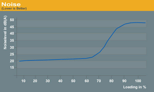
To measure the produced noise we have build an anechoic room in which we can measure the noise down to just 15 dB(A). There are simply no power supplies (except fanless models) that can reach this level under this sort of test, but at the same time we will be able to differentiate between varying levels of near-silence. In addition to the sound pressure level we will perform a spectrum analysis to show the different levels of noise produced by the fan at various frequencies.
Sample Noise
The Microphone
To get precise measurements of the noise we need something more than your typical headset-microphone. Even with professional microphones there are big differences which can result in a bad reading. There are many kinds of microphones which are totally inappropriate for test measurements of power supplies or other components. Cardioids-type microphones are pretty much useless since they are designed for directional use within a bigger space and not at all for short distances. The only microphones appropriate for these kinds of measurements are free-field microphones.
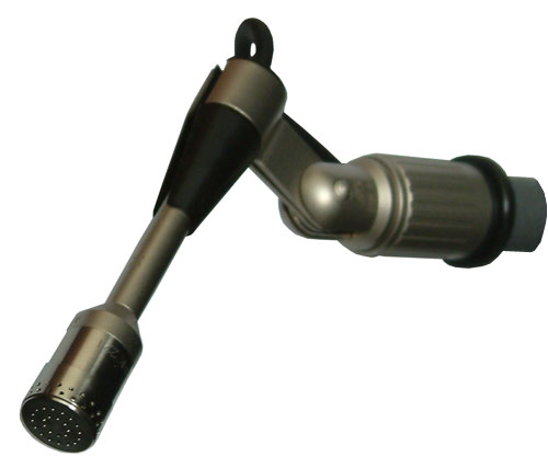
Our Microphone is a 0.5" free-field condenser measuring capsule from the renowned German specialist Microtech Gefell.
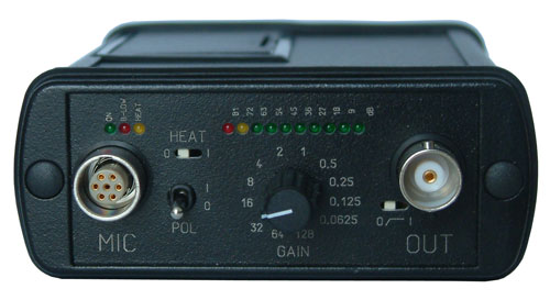
Microtech Gefell is also the manufacturer of our measuring amplifier. It adjusts the dynamic range of the measuring signal to the input dynamic of the connected PC with which we are analyzing the results.
The Testing Environment
There is one flaw in testing power supplies with programmable loads and while trying to test the sound pressure levels at the same time. Because the programmable loads get very loud there is no chance to even hear the power supply on the test stand. In order to make accurate measurements of the noise levels we needed a way to separate the test unit and the programmable loads. Our solution was to build a very thick box around the unit.
We concluded that a five-layer box with a total thickness of 6" (15cm) containing two layers of wood and three layers or special foam would suffice. It is designed as a box within a box. The inner box does not touch any part of the outer box, making it difficult for acoustic noise to pass through in the form of vibration. Each box is isolated on both sides with a layer of heavy foam which is normally used to isolate engines. In the inside we have an additional layer of 4" (10cm) thick pyramidal foam on every side of the box to eliminate the acoustic waves coming from the test object.
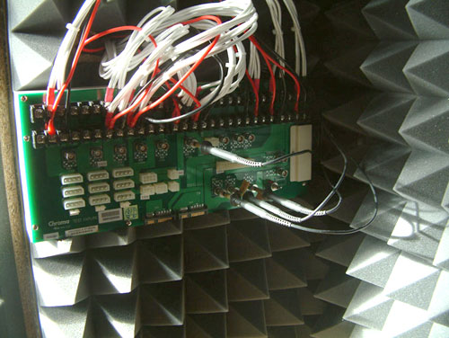
To have a completely closed system we installed the printed circuit board to which the connectors of the power supply will be attached inside the anechoic room/box. In other box designs you would need to put all the cables through the wall. Unfortunately that would result in the inside of the box not being totally isolated anymore. Our design keeps everything which needs to be connected inside of the box and maintains isolation.
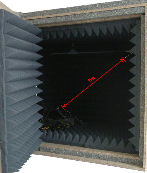
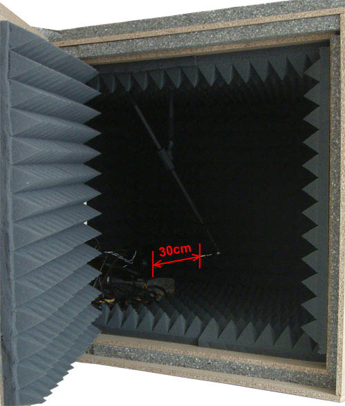
The microphone hangs on a movable stand which is connected to the roof of the box. With this we can move the microphone around in the box to the position of choice. We measure each unit from two different positions. The first is from 1m distance in conformity with normal measurements. The second position is 30cm in front of the power supply at an angle where the airflow does not interfere with the actual noise measurements.
Conclusion... for now
For many, power supplies are unfortunately still not considered an important component, but this attitude is definitively a mistake. Power supplies deliver the voltage to each and every single component in the PC and make them work. It is the heart of the system and the provided electricity works like blood in the human body. If the delivered electricity is faulty or unstable it can ruin even the greatest high-end rig instantly.
It is important that readers understand the importance of power supplies in today's PCs and we will do our part from now on to deliver the necessary tests. In addition we will explore the manufacturers themselves; good quality starts with a good engineering team that develops upcoming power supplies. We will visit the offices and factories of the manufacturers to show how and where power supplies are made.
When testing power supplies we will pay attention to important aspects of the units. It begins with the design of the PCB and the components used. A power supply might look very good from the outside but the build quality and structure inside could be just rubbish. To help determine the quality of these aspects of a power supply, we will open the test units and analyze the structure and important components on it. These days, power supply efficiency is a very important factor to consider, and it is very dependent on the components that are used. As we will see in the various reviews, better components result in improved efficiency as well as improved results in our other tests.
PCs often play an integral role in today's households. To make having them around more pleasant, it is very important to eliminate - or at least reduce - any noise pollution from the PC. By looking at the temperature of the heatsinks and the exhausted air and by checking the fan speed, we can get a better idea of what design decisions have been made in regards to reducing noise, as well as whether or not the design decisions are effective. Nothing is worse than a noisy power supply that still gets hot!
As a final thought, our tests are based on today's applications and circumstances, but we will also be pushing power supplies to their limits. If a power supply fails during testing, that doesn't necessarily mean it's a truly bad design. Failures can occur for a variety of reasons, and we will be sure to provide a detailed explanation of any failures, why they happen, and what they mean in the broader view of things. For example, we may see a few PSUs that perform extremely well, provided you don't exceed certain loads on some of the voltage rails.
Now that we have introduced our test equipment all that remains is to commence the actual testing and publication of results. Of course, that's not the end of the story, and we will be able to build opinions that will shape our future testing. We took a great deal of time planning, developing, and building our power supply test lab and we are sure it will do what it was built for: to deliver the most accurate and meaningful results possible. Stay tuned as we begin to cover this important area of computer components.


