
Original Link: https://www.anandtech.com/show/180
Sitting at home, typing on my custom built Pentium II system, an irony which wasn't apparent to me previously made a surprise appearance in front of me. With all of the resources out there that help you decide what components to build your next computer or upgrade out of, there are very few places to gain the knowledge needed to actually put together an entire PC from scratch. The irony of the matter lies in the fact that there are hundreds of people graciously willing to tell you what to put in your system, but very few tell you how, which is why I decided to put together a short little guide on how to build a computer.
This guide takes into assumption that you have already purchased all the parts for your new system and that all which remains is for the physical assembly and configuration to take place. If you are still unsure about which components will go in your system, you will want to finalize your decision on those first, then approach the idea of constructing the system. AnandTech is not responsible for any damaged caused to your system as a result, either directly or indirectly of the methods described in this guide.
Before proceeding with the building process you want to clear out a small portion of a fairly dust free room, hard wood floors are a plus however a wooden table or a workbench is even better. You want to lay out all of the components you have just received on a table near you, as well as place all appropriate screws, mounting brackets, as well as device driver diskettes by the items they correspond to. You will need a Phillips head screw driver, however a flat headed screw driver, and anti-static wrist strap, additional screws, needle nose pliers, and a computer toolkit are optional.
With all of that taken care of, let's start on that system shall we?
The Case
At the heart of every computer is the CPU, which is placed on the motherboard, which parks the peripherals, which drive the storage devices, which are stored in none other than your computer's case. While that mental diagram is remnant of playing a little one on one with your neighborhood point guard it is as simply put as it can be. The case should be the first thing that is opened and inspected before proceeding with any custom built system. Removing the case from its often bulky and large box, you want to make sure that there is no external damage to the case itself. When most vendors ship any order that contains an order for a system case, without the request to pre-install or configure any components in the case, the case itself is often shipped in a separate package so be sure that you do in fact receive two packages from the delivery man. The reason for shipping a case in a separate box is to prevent any sort of physical damage to the other parts shipping with your order. If everything looks ok from the interior, you will want to take a peak at the inside of the case to make sure that you have the proper screws, power cables, standoffs, etc... that are necessary to proceed further.
If your case happens to have a lock on it you will want to check the packaging to find the keys if they weren't attached to the case in any way. In the unfortunate event that the keys didn't ship with the case and the door happens to be locked, most suitcase keys will work fine provided that the key hole isn't spherical, in which case you will want to remove the external housing of the case and unlock the door from the inside by pushing the locking lever out of its resting place. As paranoid as that may seem, it does happen, and sometimes unlocking your case can be a major pain without the proper keys.
Depending on the type of case you purchased, the housing will either come off from the back end of the case or from the front. In the latter situation, the front panel of the case usually pulls off exposing anywhere from 4 - 8 screws which attach the housing to the case's frame. This is how most Enlight cases open. If your housing can be removed by pulling it off of the rear of the case then you want to look at the back of the case and remove the individual screws (once again anywhere from 4 - 8 depending on the type/size of case) therefore freeing up the housing for removal. The most user friendly cases are those which allow you to individually remove portions of the housing, such as the Supermicro design which splits the housing into three sections: a left door, a right door, and a top. Each of those three sections can be removed individually for easy access to any components contained within the case.
Taking a look at the inside of your case, you want to check for a bag of screws/stand-offs, a power cable, keys (if applicable), and any extras such as feet for the case or an alternative ATX backplate if you have an ATX case. If you do happen to have an ATX case, and provided everything looks physically ok on the inside of the case, you will want to examine the 2 - 4 pin power switch wire which will usually be the longest wire in the case running directly from the ATX power switch. Make sure that the cable hasn't been cut and that it is securely attached to the power switch (all of the pins that are taped to the connectors on the switch should be covered up, either by electrical tape or some sort of metal casing). Remove all foreign parts from the interior of the case, unscrew/remove any standoffs that have been pre-installed, and make sure that the motherboard plate is free of all obstructions.
There should be three main types of screws included with your case, the first is your standard chassis screw which is used to attach standard devices and peripherals to the chassis, i.e. video cards, hard drives etc... The second is a screw with a smaller diameter than your standard chassis screw which is mainly used to attach your motherboard to the third type of screw that should've been provided with your motherboard, the stand-offs. Standoffs are screwed onto the motherboard tray of your case and separate the motherboard from the tray by about 1/8". In order to hold the motherboard in place, standoffs contain a threaded opening at the top which will accept the second type of screw discussed above through the holes on your motherboard. Owners of AT cases will find that usually only two or three metal stand-offs are included with their case, while ATX cases ship with close to 10 or 12 metal stand-offs. The reason for this is that AT cases usually rely on the cheaper and more flimsy plastic stand-offs that snap into your motherboard, while this approach is a bit more clumsy than the metal standoff approach it is something you should be prepared for.
Now that the case is clean and ready for installation, set it aside as we prepare the motherboard for installation.
The Motherboard
The motherboard is a very intimidating device for most first time builders, however it shouldn't. Once you get used to setting jumpers, your comfort level with installing a motherboard will increase tremendously. While preparing your motherboard for installation, it is best to do so on a wooden table, or even on the box of the motherboard itself. Do not prepare the motherboard on any carpeting or other static carrying surfaces. It is always best to proceed from this step forth with an anti-static strap on your wrist although one isn't required. Most motherboard vendors will provide one free of charge, just be sure to ask for it.
The first thing you want to do is remove the motherboard from its box and its anti-static bag, place the board itself on a hard surface which is covered by the anti-static bag you removed it from. Quickly inspect the board and make note of any protruding wires that appear to be soldered on as well as any damaged components. If the motherboard appears to be physically damaged, do not risk installation, call up your vendor and request a replacement. If everything appears to be ok, then you can proceed to the next step. Verify that you were sold the proper motherboard, double check the markings on the chipset as well as those on the motherboard's PCB (printed circuit board) itself.
Next, familiarize yourself with your User's Manual, there is no point in reading the entire manual word for word, but familiarize yourself with the introduction to the manual as well as the installation portion. It is always good to take a look at the troubleshooting section to identify any problems you may experience before they actually occur. Being prepared for a problem usually removes some of the intimidation building a new computer may provide you with. The next step involves setting jumpers, so if your motherboard is jumperless you can skip this next paragraph.
Keep in mind that a computer operates using a binary number system, meaning that in any one scenario you have two options, a 1 or a 0, on or off, up or down, right or left, and so on and so forth. In the case of setting up your motherboard, the same rule applies. In order to maintain compatibility with the many different types of processors and memory that are out on the market today, the motherboard is one of the most flexible devices in your system. With a few alterations of the current of electricity flowing through your board you can add support for new CPU's and other such things. This is exactly what setting a jumper does.
| A jumper is nothing more than a set of 2 or more pins which carries an electric current for the purpose of configuration. When a jumper is left unmodified, there is no current running through the two pins, therefore the circuit remains broken and the value of the setting is off. A jumper in this state is referred to as being Off or uncapped. So how do you change the state of a jumper? You turn it on by placing a plastic cap on the jumper that contains a small wire on the inside which connects the pins and allows current to run through them. In this case, the jumper is referred to as being on or capped. That is the most elementary example in which case there are only 2 pins to a jumper, however in some cases there may be 3 or 4 pins. In those cases the jumper settings are referred to according to the pins that remain on or capped. |  |
| For example, if jumper JP1, a 3 pin jumper, was supposed to be set at '1-2' as documented in the manual, pins 1 and 2 would be capped. However if it was supposed to be set at '2-3' then pins 2 and 3 would remain capped. The combination of the jumper settings on your motherboard is what configures your system on the lowest of levels. It is what controls the amount of voltage that should be fed to your CPU as well as the actual clock speed your CPU will run at. It is best to think of the jumpers on a motherboard as a wall of light switches. On this wall of light switches, a certain combination must be attained in order to turn on the lights you wish to have on. By changing the position of the light switches (placing them in the on or off position) you control the lights, and by properly modifying all of the switches as a whole you can turn on the lights you wish to have on. The same thing applies to configuring a motherboard, except for that the light switches represent jumpers and the desired lighting configuration represents the system configuration. Not too difficult now are they? Some motherboards even take it one step further by replacing jumpers with tiny switches known as dip-switches, these switches operate the same way jumpers do except for the fact that you don't cap the switches, you simply flip them on or off, just like a light switch. | |
With that out of the way, we can get to actually configuring the motherboard. The first thing you want to do is set the core voltage for your processor. Usually the markings on the top of your CPU will reveal the core and I/O voltages your processor was meant to run at. In the event that it doesn't, here is an abridged table of voltage settings for various processors:
Processor |
Recommended Voltage Settings |
| Intel | |
| Pentium Classic - P54C | 3.3v/3.52v (Single Voltage - Core=I/O) |
| Pentium MMX - P55C | 2.8v (Dual Voltage - I/O=3.3v) |
| Pentium II - Klamath | 2.8v (Dual Voltage - I/O=3.3v) |
| Pentium II - Deschutes | 2.0v (Dual Voltage - I/O=3.3v) |
| Pentium II - Celeron | 2.0v (Dual Voltage - I/O=3.3v) |
| Pentium II - Xeon | 2.0v (Dual Voltage - I/O=3.3v) |
| AMD | |
| K5 | 3.3v/3.52v (Single Voltage - Core=I/O) |
| K6 - 166/200 | 2.9v (Dual Voltage - I/O=3.3v) |
| K6 - 233 | 3.2v (Dual Voltage - I/O=3.3v) |
| K6 - 266/300 | 2.2v (Dual Voltage - I/O=3.3v) |
| K6-2 | 2.2v (Dual Voltage - I/O=3.3v) |
| Cyrix | |
| 6x86 | 3.3v/3.52v (Single Voltage - Core=I/O) |
| 6x86L | 2.8v (Dual Voltage - I/O=3.3v) |
| 6x86MX | 2.9v (Dual Voltage - I/O=3.3v) |
| M-II (PR300 and lower) | 2.9v (Dual Voltage - I/O=3.3v) |
Using the User's Manual as your reference guide, locate the voltage selection jumpers or dip switches and configure them properly as documented in the manual. The next step is to set your Front Side Bus (FSB) frequency as well as your CPU's clock multiplier. This should also be inscribed on your CPU, or documented in your User's Manual, in the event that it isn't here are some frequently used settings:
| Clock Speed | FSB Frequency (Bus Speed) | Clock Multiplier |
| 75MHz | 50MHz | 1.5 |
| 90MHz | 60MHz | 1.5 |
| 100MHz | 66MHz | 1.5 |
| 110MHz | 55MHz | 2.0 |
| 120MHz | 60MHz | 2.0 |
| 133MHz | 66MHz | 2.0 |
| 150MHz | 60MHz | 2.5 |
| 166MHz | 66MHz | 2.5 |
| 180MHz | 60MHz | 3.0 |
| 187.5MHz | 75MHz | 2.5 |
| 200MHz | 66MHz | 3.0 |
| 225MHz | 75MHz | 3.0 |
| 233MHz | 66MHz | 3.5 (1.5) |
| 266MHz | 66MHz | 4.0 |
| 300MHz | 66MHz | 4.5 |
| 300MHz | 100MHz | 3.0 |
| 333MHz | 66MHz | 5.0 |
| 333MHz | 95MHz | 3.5 |
| 350MHz | 100MHz | 3.5 |
| 400MHz | 100MHz | 4.0 |
| 450MHz | 100MHz | 4.5 |
Once again, with the aid of your user's manual, select the appropriate FSB frequency and clock multiplier for your CPU. Although it may be tempting to now, do not overclock your system until you get it up and running perfectly first, then you may attempt to overclock it. The next step is configuring all other jumpers that are specifically documented in the manual. If your motherboard has both AT & ATX power connectors on it be sure to set the appropriate jumper according to what type of power supply you will be using. If your chipset supports the asynchronous operation of your SDRAM clock speed, then be sure to set jumpers associated with that feature as well. The general rule of thumb here is to remember that if the manufacturer spent time printing info on how to set it, it is probably worth your attention.
Processor & Memory
Still working on the same surface that you were working on before, you want to next start on the processor installation. If you have a Socket-X based processor that interfaces with your motherboard using a ZIF (Zero Insertion Force) socket, then the process is a bit more detailed than if you're installing a Slot based processor.
If you're installing a socketed processor you should first check to see if any of the processor's pins have been bent during shipping or handling. If the answer is yes, then you need to make a quick judgement as to how extensive the damage is. If there are only a few pins that are bent, and the severity of the bends isn't too great then a tiny flat-headed screw driver will do the trick (but be VERY careful). If a great number of the processor's pins remain bent then you should probably contact your vendor and request a replacement as tinkering with your chip in any manner usually voids the warranty.
To install the processor in a ZIF socket, lift up the lever next to the socket so that it is now perpendicular to its original resting position. Line up the processor's pins with those on the ZIF socket, making sure that pin 1 (the pin on the grooved corner) on the processor matches up with pin 1 on the motherboard. With the processor lined up, rest it on top of the socket and lightly apply pressure to seat it in place. If the processor refuses your attempts to insert it into the socket, do not force it in (there is a reason the socket is referred to as a Zero Insertion Force socket) and double check to make sure that all of the pins are straight and that the processor is lined up properly with the socket then reattempt the installation. Depending on the layout of your motherboard/case you may or may not want to attach the CPU's heatsink/fan assembly now, a bit of thermal compound on the face of your CPU (not too much, it shouldn't be dripping off the sides of the CPU) will help thermal conductivity and cooling, so you may want to apply some of that as well.
To install a Pentium II class processor in a Slot interface, you will first want to attach the heatsink/fan assembly to the processor. Attach the CPU retention kit to your motherboard if it hasn't already been attached, and install the heatsink support (optional) device to the motherboard as well. If the CPU retention kit attaches to your motherboard via screws, do not over tighten the screws, just tighten them enough that the retention kit stays in place and doesn't wiggle around. After this has been complete, you can pop in the processor card until it rests firmly in the retention brackets and locks into place. The processor can only be installed in one direction so there is no chance of screwing up here.
Next comes the memory installation, this step can be performed after you install your motherboard in the case depending on, once again, the layout of your motherboard and the style of your case. All DRAM can only be installed one way, for 30 & 72-pin SIMMs, stick the module in at a 45 degree angle, and slowly push it to a 90 degree angle where it will click into place. 168-pin DIMMs should be installed at a 90 degree angle to the motherboard and pushed until it clicks into place.
With all that installed, go back and double check all jumper settings, all connections, and make sure that both the processor and memory are installed properly.
The Construction Begins
In that same relatively dust free location you've been working in, lay your case on its side so that the motherboard tray is exposed to you. If you have an ATX case and wish to install a new ATX I/O backplate then this is the time do so. Personally, I prefer leaving the backplate off, however if you feel more comfortable with it on then you can go ahead an install it now. Most AT cases do have a removable motherboard tray, in which case you will want to remove the motherboard tray for this part of the installation.
Place the motherboard over the tray and estimate how many stand-offs (metal and or plastic) you will need to fasten the motherboard to its tray. Out of the bag of screws that came with the case, set aside exactly as many metal and plastic stand-offs as you counted. Now, you want to set aside as many screws that will be used to attach your motherboard to the standoffs as you have metal standoffs. The reason for setting these screws apart now is to keep track of the metal standoffs, as you may be able to guess, no metal object should come in contact with your motherboard's PCB. So if you accidentally place a metal standoff underneath a part of your board that doesn't contain a screw hole you will short out the motherboard the minute you apply power to it. By setting aside exactly the same amount of screws as you have metal standoffs, after attaching the board to the standoffs, if you have any remaining screws you know you missed a standoff and you should immediately double check your mounting. This will prevent you from accidentally shorting out the board and may even save you the cost of replacing the board as no vendors will replace a board damaged by a mistake on your part.
Metal standoffs simply screw into the motherboard tray itself, while plastic standoffs sort of snap into the tray as well as the board. The main purpose of both types of standoffs is to make sure that no part of the motherboard ever touches the metal tray underneath it, after you have secured the board to the tray make sure that no part of it could possibly touch the tray unless extreme force were applied to it. Now you want to fasten your motherboard to the tray and tighten all screws, remember not to make the screws too tight, a power screw driver may be a little overkill here. If everything checks out here, you're ready for the next step. |
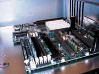 |
It's time to connect your power supply to your motherboard, first you want to make sure that the power supply is not connected to an outlet and all power cables are disconnected. After checking on that, you will want to grab the internal power supply cable and plug it into the motherboard. ATX power supplies offer a 20-pin P/S block that easily fits into the power connector, while AT power supplies use 2 separate 5-pin connectors. Both types of connectors can only go in one way, the general rule of thumb here is to remember that when plugging in AT P/S connectors you should never cross the black wires. There is a set of two black wires on each 5-pin connector, the black wires from each connector should be placed next to each other when plugged into the motherboard. Any other orientation will cause your motherboard to short out and could lead to more damage.
With the power supply connected, the next step is connecting all fans to their appropriate power supply connectors. If your fan has a three pin power connector, then the receptacle you are looking for will be a 3-pin port on your motherboard usually with a white or brown casing around half of the connector. If your fan requires a standard 4-pin 5V power connector then you can simply grab a free connector stemming from the power supply and plug it into there. If you have a secondary case fan then the same applies, while connecting additional devices onto power cables it is best to avoid connecting those onto a cable which has already been occupied by a secondary case fan as they do tend to be power hogs.
Before turning your computer on for the first time you'll want to pop in your video card. If you're using an AGP video card, simply remove the slot cover in front of your AGP slot and install the card there. If you're using a PCI video card then you probably want to choose the slot furthest away from the ISA slots. Plug in your monitor, keyboard (remember that on ATX cases, the keyboard port is the one physically closest to the floor of the motherboard tray), and power supply cable and fire up the system. If everything went ok your monitor should eventually switch out of suspend mode and you should see your BIOS initialize as the memory count starts up. Try getting into the BIOS, don't save any settings, but just make sure that your keyboard is working properly and that your video connection is ok as well. If you don't get anything on your screen after a reasonable period of time (30 seconds should be the maximum time between powering on your system and the first video display) power down your system, check all connections and try again. Always pay attention to the fans in your system, if they don't spin up then immediately remove all power to the case and make sure you're not shorting anything out. Double check that the processor has been inserted properly and that the motherboard isn't in contact with any foreign pieces of metal.
If that bootup worked out ok, pat yourself on the back as the hardest part of building your system is now over and you're ready to complete the building process.
Storage Device Installation
Installing your storage devices isn't a difficult task at all. The first thing you want to do is to make sure that all jumpers on your hard drive(s) and CD-ROM drive(s) are configured properly. Provided you have an EIDE/IDE Hard Drive you have three basic jumper options:
Master without a Slave
Master with a Slave
Slave
| If your drive is a Master without a Slave, then it is the only device on its cable and is therefore the only device on its channel. A Master with a Slave would be a drive that isn't the only device on its cable, but happens to be the primary device on its channel. Usually you want all hard drives and other such storage devices to be masters, with all CD-ROM drives set as slaves. A device set as a Slave alone is a drive that has another device on its chain which is set to Master with a Slave. The best route to take is to always try to give all peripherals their own channel, for example, if you're installing a hard drive and a CD-ROM drive you would want both to be Masters without a Slave with one on each of the 2 EIDE channels. Jumper settings can be found in your storage device's documentation. The setup for SCSI drives is a bit more difficult, and in which case you should consult your SCSI controller's User's Manual for a detailed explanation of termination settings and SCSI ID's. | 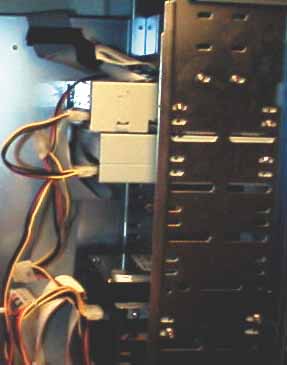 |
Once all the jumpers are set properly you want to find a home for your new hard drive, realistically you can chose just about any area in your case however there are certain places you want to stay away from. It is usually best to keep the CD-ROM drive near the top of your case away from any other devices that generate large amounts of heat as the large size of a CD-ROM drive will tend to act as a heat trap for re-circulated air. Hard drives, regardless of size, should always be kept as far away from other components and storage devices as possible. Hard drives often generate more heat than you would imagine, especially with 7200RPM and 10,000RPM drives growing in popularity, cooling becomes a major issue. You want to place your hard drive in well ventilated and well cooled areas of your case. Some cases do have hard drive bays directly above or below their power supplies, however you should never install a hard drive in a bay close to a power supply. Keep in mind that a power supply is much like a large magnet, and if you place anything magnetic near a magnetic storage device such as a hard drive, well, you know what happens. You can kiss those documents good bye if you plant a hard drive next to a power supply, while the process may be a slow one, data corruption has an incredible chance of resulting in a situation like this one.
Grab a couple of screws, if possible you want to use the ones that came with your hard drive/storage device, and attach the drive to your case. You want to make these screws a bit tighter than the ones you used for your motherboard, but once again, not too tight. Make sure that you line up the front panel of any devices with an opening on the front with the rest of your case. On the inside, connect all cables to your motherboard or controller card keeping in mind that pin-1 of any hard drive cable (the red pin) will always be the one closest to the hard drive's power connector. Pin-1 on the motherboard (or controller card) is usually represented by a small number on the PCB, and of course you'll find it in the manual. SCSI cable connection is a bit different from your standard IDE setup however you shouldn't let it intimidate you. Basically, with SCSI devices, there are two ends to every chain: a start and a finish. Both of those ends must be terminated, which is accomplished by a device known as a terminator. If your SCSI device is connected at the end of your SCSI chain it must either have an on-board terminator or it must have an in-line terminator installed on the cable, if the chain isn't properly terminated you will experience problems during operation (i.e. drives not being detected, diagnostic errors, no host adapter found errors). For your CD-ROM/DVD drive, don't forget to install a CD-Audio cable running from the back of your CD-ROM/DVD drive to your sound card otherwise you won't be able to listen to audio CD's on your computer without the use of headphones. Don't forget to plug in the 4-pin power cables, they can only be installed one way on hard drives so don't worry about screwing something up at this point.
Installing your floppy drive shouldn't pose much of a problem, no jumpers to set, just line it up with the screw holes on your chassis and attach a few screws. The same pin-1 rule applies here, pin-1 of your FDD cable should be the one closest to the power connector. The floppy drive uses a smaller 4-pin power connector, while the connector should only be able to accept power cables in one orientation, with a little force a cable could be inserted the wrong way. Take special precautions to make sure that you don't insert the cable the wrong way, if you smell/see smoke after booting up your machine immediately unplug it and check all power connections especially those that could possibly be backwards.
Peripheral Installation
| There isn't a big trick to installing peripherals, simply find opens slots and occupy them. If possible you don't want to populate the last PCI slot (the one closest to the AGP slot) and the AGP slot at the same time as they share an IRQ, something not all devices are comfortable with. Some devices don't mind sharing an IRQ with an AGP card while others just simply refuse to boot. To stay on the safe side, leave that slot unpopulated if possible, if not, find out which card works best in there and use that card in the slot. | 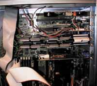 |
You will want to keep hot peripheral cards, such as Voodoo2 boards as close to additional cooling devices as possible. You also want to make sure that they aren't being surrounded by any cables or anything else that may prevent the flow of cooled/re-circulated air throughout the system.
Other than that, just keep in mind that full length cards can only fit in full length slots and that no foreign metal objects should touch the PCB of any of your peripheral expansion cards either, not just the motherboard.
Covering the Case
| Now it's time to cover your case (no need to screw it back together since, if you're anything like most tweakers, you'll be back in there in a few days to check up on things), plug everything in, and fire up your system. That should have new meaning now that you've actually constructed an entire computer yourself, not too difficult now is it? | 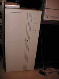 |
Anand's Personal System
| CPU | Intel Pentium II 333 clocked at 100 x 4.0 |
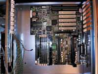
| Motherboard | Supermicro P6DGU |
|
Intel 440GX |
|
5/2/1 |
| RAM | 256MB (2 x 128MB Corsair PC100 DIMMs) |
| Monitor | Panasonic PanaSync E21 21" Monitor |
| Video | Matrox Millennium G200 (16MB) |
|
Dual Diamond Monster 3D-2 (12MB) SLI |
| Hard Disk Controller | On-Board Adaptec 7890 Ultra2 SCSI |
|
18.2GB Ultra2 SCSI Seagate Cheetah - 10,000RPM |
|
Plextor UltraPlex 32X SCSI Ricoh 2X/6X SCSI CD-RW (External) Smart & Friendly 4X/12X SCSI CD-RW |
| Sound | Altec
Lansing USB Speakers Diamond Monster Sound MX200 |
| Joystick | Microsoft Sidewinder Gamepad |
| Modem | Cardinal Internal 3440 56K X2 Fax Modem |
| Network | Linksys 100Mbps PCI Ethernet Card |
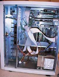
| Case | Supermicro SC801-A w/ Dual 300W Power Supplies |
| Operating Systems | Microsoft Windows 98, Windows NT |
| Keyboard | Microsoft Natural Keyboard (USB) |
| Mouse | Microsoft Intellimouse Pro (USB) |
| External Hubs | 4 Port Linksys 10/100Mbps Ethernet Hub 4 Port Belkin USB Hub |
Pictures
 |
 |
 |
 |
 |
 |
Click to Enlarge


