Original Link: https://www.anandtech.com/show/15783/the-supermicro-h11dsi-motherboard-review
The Supermicro H11DSi Motherboard Mini-Review: The Sole Dual EPYC Solution
by Dr. Ian Cutress on May 13, 2020 8:00 AM EST- Posted in
- AMD
- Motherboards
- Supermicro
- Naples
- EPYC
- 10GbE
- Rome
- H11DSi
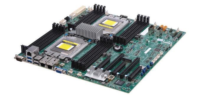
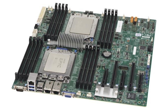
Users looking to build their own dual EPYC workstation or system, using completely off-the-shelf components, do not have a lot of options. Users can buy most of the CPUs at retail or at OEM, as well as memory, a chassis, power supplies, coolers, add-in cards. But the one item where there isn’t a lot of competition for these sorts of builds is in the motherboard. Unless you go down the route of buying a server on rails with a motherboard already fitted, there are very limited dual EPYC motherboard options for users to just purchase. So few in fact, that there are only two, both from Supermicro, and both are called the H11DSi. One variant has gigabit Ethernet, the other has 10GBase-T.
Looking For a Forest, Only Seeing a Tree
Non-proprietary motherboard options for building a single socket EPYC are fairly numerate – there’s the Supermicro H11DSL, the ASRock EPYCD8-2T (read our review here), the GIGABYTE MZ31-AR0 (read our review here), or an ASUS KNPA-U16, all varying in feature set and starting from $380. For the dual socket space however, there is only one option. The Supermicro H11DSi, H11DSi-NT, and other potential minor variants, can be found at standard retailers from around $560-$670 and up, depending on source and additional features. All other solutions that we found were part of a pre-built server or system, often using non-standard form factors due to the requests of the customer those systems were built for. In being the only ‘consumer’ focused motherboard, the H11DSi has a lot to live up to.
As with other EPYC boards in this space, users have to know which revision of the board they are getting – it’s the second revision of the board that supports both Rome and Naples processors. One of the early issues with the single socket models was that some of them were not capable of Rome support, even with an updated BIOS. It should be noted that as the H11DSi was built with Naples in mind to begin with, we are limited to PCIe 3.0 here, and not the PCIe 4.0 that Rome supports. As a result, we suspect that this motherboard might be more suited to users looking to extract the compute out of the Rome platform rather than expanded PCIe functionality. Unfortunately this means that there are no commercial dual socket EPYC motherboards with PCIe 4.0 support at the time of writing.
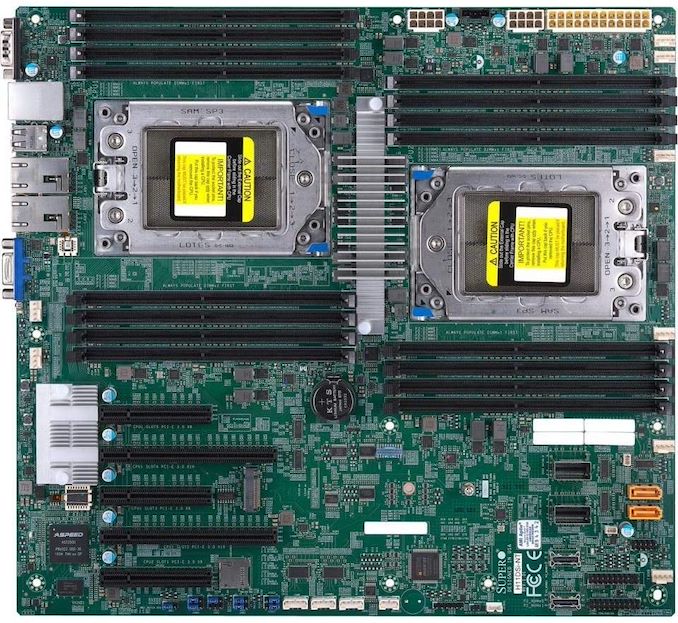
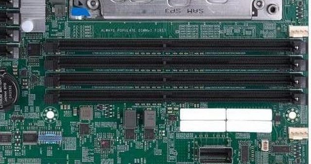
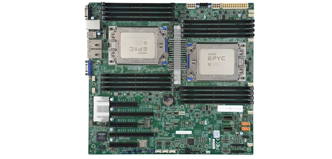
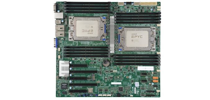
The H11DSI is partly E-ATX standard and part SSI-CEB, and so suitable cases should support both in order to get the required mounting holes. Using the dual socket orientation that it has, the board is a lot longer than what most regular PC users are used to: physically it is one square foot. The board as shown supports all 8 memory channels per socket in a 1 DIMM per channel configuration, with up to DDR4-3200 for the Revision 2 models. We successfully placed 2 TB of LRDIMMs (16 * 128 GB) in the system without issues.
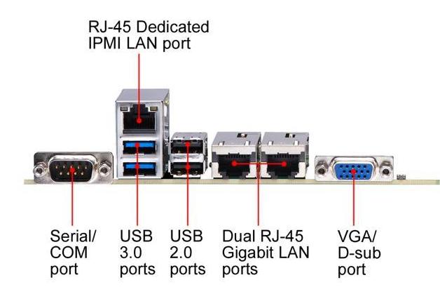
As with almost all server motherboards, there is a baseband management controller in play here – the IPMI ASPEED AST2500 which has become a standard in recent years. This allows for a log in to a Supermicro interface over the dedicated Ethernet connection, as well as a 2D video output. We’ll cover the interface on the next page.
Ethernet connectivity depends on the variant on the H11DSi you look for: the base model has two gigabit ports powered through an Intel i350-AM21 controller, while the H11DSi-NT has two 10GBase-T ports from the Intel X550-AT2 on board. Due to this controller having a higher TDP than the gigabit controller, there is an additional heatsink next to the PCIe slots.
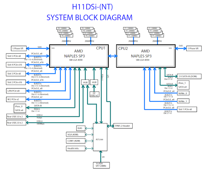
The board has a total of 10 SATA ports: two SATA-DOM ports, and four SATA ports from each CPU through two Mini-SAS connectors. It’s worth noting that the four ports here come from different CPUs, such that any software RAID across the CPUs is going to have a performance penalty. In a similar vein, the PCIe slots also come from different CPUs: the top slot is a PCIe 3.0 x8 from CPU 2, whereas the other slots (PCIe 3.0 x16/x8/x16/x8) all come from CPU 1. This means that CPU 2 doesn’t actually use many of the PCIe lanes that the processor has.
Also on the storage front is an M.2 x2 slot, which supports PCIe and SATA for Naples, but only PCIe for Rome. The power cabling is all in the top right of the motherboard, for the 24-pin main motherboard power as well as the two 12V 8-pin connectors, one each for the CPUs. Each socket is backed by a 5-phase server-grade VRM, and the motherboard has eight 4-pin fan headers for lots of cooling. The VRM is unified under a central heatsink, designed to take advantage of cross-board airflow, which will be a critical part in any system built with this board.
We tested the motherboard with both EPYC 7642 (Rome, 48 core) processors and the latest EPYC 7F52 (Rome, 16 core high frequency) processors without issue.
BIOS Overview
As with most server motherboards, the BIOS interface is the old-style black/blue/white on grey. This is an Aptio utility on top of an American Megatrends base. There are a number of options here that would often be hidden in a regular consumer motherboard. We’ve chosen a few of the procedural highlights for this review.
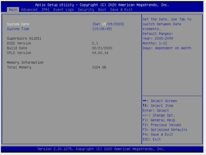
The main entry point is the Main screen, which states the BIOS version and build date, as well as the memory installed, but not a lot else. Typically we prefer to see also the CPUs listed here, if only for a quick visual check when entering the BIOS.
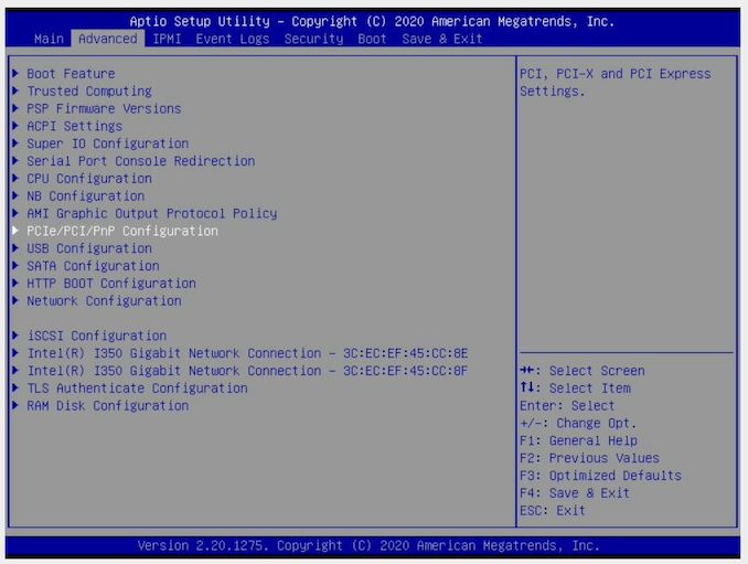
The screen with most of the functional options is Advanced, as shown here. There are sub-menus for most of the functional elements on the board, including Boot, Security Processor, IO, CPU/NorthBridge (DRAM), USB, SATA, Networking, and even a RAMDisk option.
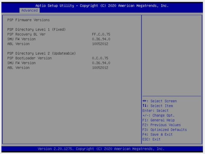
Under the PSP menu shows the hierarchy and firmware versions for PSP support.
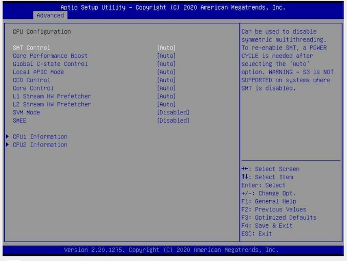
For the CPU configuration, we still haven’t seen what CPUs are installed, but here users can select to enable/disable simultaneous multi-threading, core performance (fixed frequency or fixed power), C-state control, Core Complex control, and other features like the hardware prefetchers (some software works better when these are disabled, depending on how the software is written).
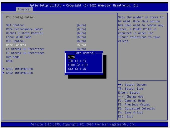
For the Core Control, users can select how many cores per CCX need to be enabled. The full L3 of the chiplet is still available, so this can be used to optimize software that can benefit from more L3 per core (if you didn’t buy a cheaper EPYC to begin with).
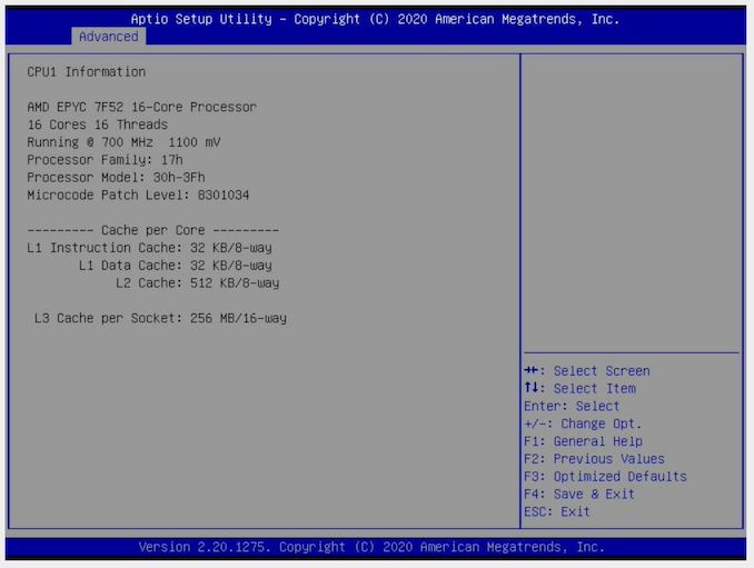
Here we get to the CPU information, finally. Our 7F52 here had SMT disabled, and is showing as running at 700 MHz while in the BIOS. The chip has a nominal operating voltage of 1.1 volts.
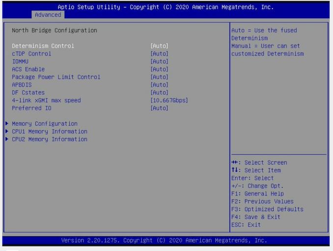
Under the North Bridge configuration is where we get some of the IO options as well as Memory configurations. Included here is the determinism option (for when QoS is required), as well as cTDP options for processor models that support it.
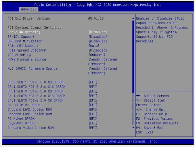
Users looking to have some high-end GPU compute will need to enable 4G Decoding, in the PCIe sub-menu. Users can also manage how the PCIe devices and slots are managed here, including the onboard video.
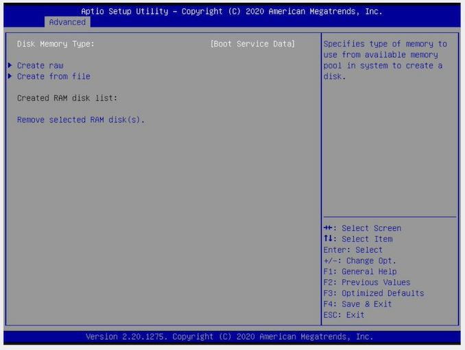
This board also supports RAMDisk operation, and like other RAMDisks this data is lost when power is lost.
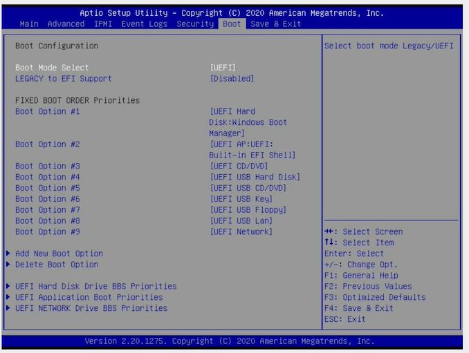
Boot options are extensive, with the board supporting boot from just about anything. Here we disabled Legacy boot due to some detection issues with our USB devices.
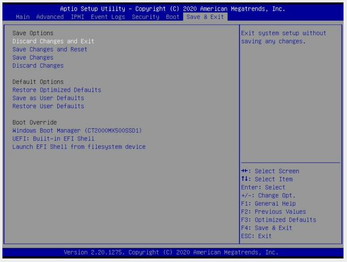
The ever critical Boot Override is also present. Users will need to press F11 in order to get to the boot menu during boot, or they can enter the BIOS and select it here.
IPMI
I often find with dual socket motherboards that some extra love and care is needed to get them to work properly, especially because normal troubleshooting techniques we get on consumer motherboards (like a two-digit debug) aren’t present. This is where the baseband management controller comes in, and being able to remote access the system over the network.
One of the new features that Supermicro has implemented here, due to California law, is that no system can be shipped with a default admin/password combination any more. The H11DSi still has the main admin user as ADMIN, but the password is printed on a sticker on the motherboard – you’ll find it in the area just below the DRAM slots. Ours was a 10-letter password in all caps.
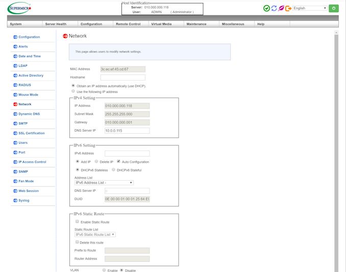
By default the IPMI interface will accept a DHCP IP, although this can be changed. Once entered, we get Supermicro’s latest interface.
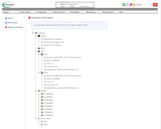
Within the first few pages is the system as detected, and we can see here it detects the two processors as well as the memory and BIOS versions. Users can update the BIOS and BMC through this interface.
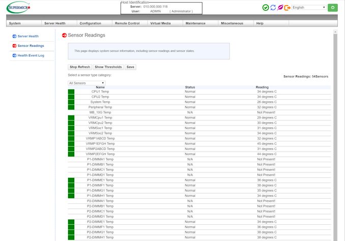
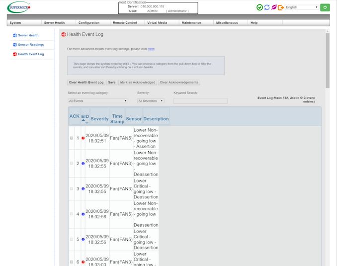
There are 54 sensors on the motherboard, relating to temperature, voltages, and fan speeds. Through the IPMI, users can set high and low limits for any of these sensors. Any discrepancy from the expected values is recorded in the health log.
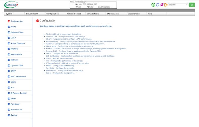
The big area for the IPMI is the configuration tab, which offers access to networking and server controls.
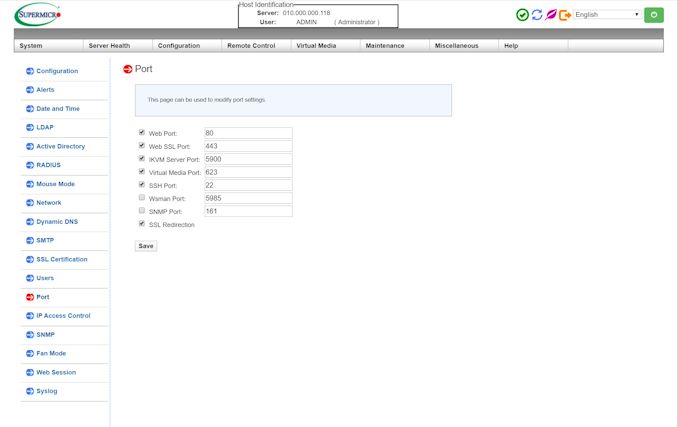
Ports can also be set for the various use cases.
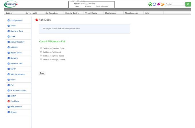
One thing to note with this motherboard is the fan speeds. While there are eight different 4-pin fan headers on the board, the amount of control offered to the end-user is pitiful. There is nothing in the BIOS to allow users to control the fan speed – instead a user has to access the IPMI, and even then the options are limited to four:
By default this is set to Optimal Speed, but a modern system should be able to support fan curves. It seems odd that consumer motherboards are by far ahead of the curve here, as fan control might be something required for a server board depending on the environment.
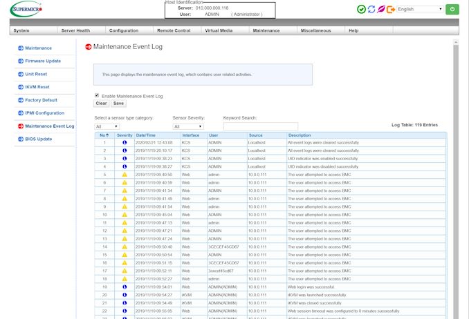
Like most server motherboards, there is also a service log to show what was changed and when.
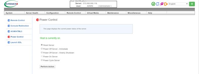
For remote control/iKVM, the interface supports only a HTML5 login, which is how we accessed the system. The interface allows for full power control, including a software shutdown mode.
System Benchmarks
On a system like this, there’s not a whole lot to emphasize through benchmarking.
Wall Power
For our power testing, we're booting into Windows and letting the system idle in the operating system for 5 minutes, then taking a reading of the power at the wall. We then fire up Cinebench R20, which probes all the threads in our dual 7F52 setup, and take the peak power from the benchmark. For this review, we've also tested a series of DRAM setups, taking a minimum/minimum of 2 x 8 GB RDIMMs (1 channel) and 16 x 128 GB LRDIMM (8-channel).
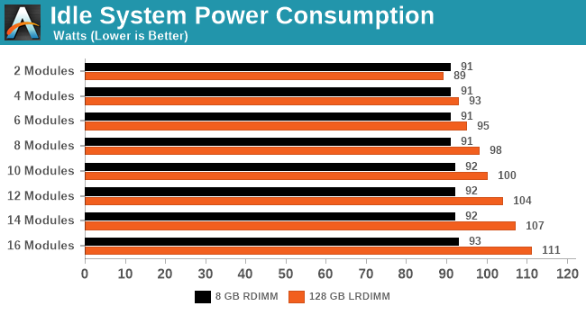
For idle power, our RDIMM arrangement doesn't cause much extra power. With the LRDIMMs, we're looking at an extra 2W per module at idle.
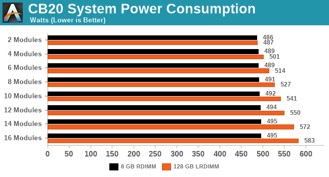
For full load, again the 8 GB DIMMs only draw fractions of a watt a piece. Moving up to the large modules, and we're realistically seeing another 7 W per module on average. When we compare the min/max, there's an extra 100W dedicated just to the memory here.
Warm POST Test
For our POST test, we take a system that has been previously booted, shut it down until all the fans stop spinning, and then initiate a power on through the BMC. The time recorded is for the initial BIOS procedure until the OS starts loading. Again with this test, we've gone through with different DRAM configurations.
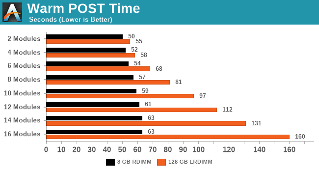
More memory means more training is required to ensure that each module will operate within a given set of sub-timings. The more capacity at play, and the more channels populated, means more time is required. At the quickest POST it takes 50 seconds, but our longest recorded POST was over two minutes.
DPC Latency
Deferred Procedure Call latency is a way in which Windows handles interrupt servicing. In order to wait for a processor to acknowledge the request, the system will queue all interrupt requests by priority. Critical interrupts will be handled as soon as possible, whereas lesser priority requests such as audio will be further down the line. If the audio device requires data, it will have to wait until the request is processed before the buffer is filled.
If the device drivers of higher priority components in a system are poorly implemented, this can cause delays in request scheduling and process time. This can lead to an empty audio buffer and characteristic audible pauses, pops and clicks. The DPC latency checker measures how much time is taken processing DPCs from driver invocation. The lower the value will result in better audio transfer at smaller buffer sizes. Results are measured in microseconds.

The DPC values for the Supermicro board are very impressive. Normally we consider here anything under 200 microseconds as a successful result, and a fresh system on the Supermicro goes well below that.
H11DSi Conclusions
The ability to provide a suitable recommendation on a product is stifled when it turns out to be the only one available for a given market. I was surprised when I started doing research on dual socket EPYC solutions as to just how few motherboards were available. The fact that the number was one was even more dumbfounding – is there really next to no market for custom off-the-shelf built dual socket EPYC systems? Over the years we’ve seen a plentiful number of dual socket Xeon offerings for each generation, but it is perhaps that the market is still getting used to EPYC is why the options are limited. In a similar line, only four single socket options exist as well.
So despite the Supermicro H11DSi and its derivatives being the only option available, if you need it then there is no other question. But if the option is between this and perhaps going to two single socket systems, it still begs the question as to whether it is good motherboard to invest in. On paper, ~$680 for a dual socket EPYC board seems like a reasonable price.
First, let us start with some of the failings. Personally I felt that the lack of fan control support was a big let-down, especially if this is a motherboard that might find its way into desktop-class chassis for workstations. The only way to access the fan control is through the web-interface IPMI, and the options are extremely basic.
The other issue on the board is simply one of layout – due to board limitations there isn’t much that can be done here, but ultimately the second CPU is underutilized. Out of the 64 PCIe lanes that it offers (the chip has 128, but 64 are being used for CPU-to-CPU links), only 8 are used for an external PCIe device. It’s almost as if this motherboard needs a separate add-on device to be able to use more of what the hardware can offer. This brings me back around to the conclusion I made on the first page – this motherboard is likely more for CPU computational use cases than anything that needs to fully use the IO of the hardware.
On the positives, the power cable layout is good for most systems, as I’ve experienced some bad power connector placement in similar boards for older systems. Having 8 fan headers, despite what I’ve said above, is a good thing as well. We successfully booted both from SATA and NVMe, and accessing IPMI through a board-specific password is something we expect all future server products to adhere to in the future. We had no issues with the latest high-end processors, the 7F02 series, as well as some of the high core count ones running some super high density memory. That price isn’t too bad either, especially if this is going to be a compute focused system with high-value CPUs inside.
It is difficult not to sound downtrodden when you have to write 'it gets recommended by default, because it's the only option'. Users looking at EPYC systems might find that single socket deployments might be in your favor - the EPYCD82T that we reviewed previously costs around the same price as this 2P Supermicro board, but makes a lot better use of the IO per socket. The Supermicro H11DSi has density in its favor, and will cater to that crowd, but there are a number of decent single socket offerings that should be explored as well.

