Original Link: https://www.anandtech.com/show/10081/wifi-testing-with-ixia-wavedevice
More Than Throughput: Next Generation Wi-Fi Testing with Ixia's WaveDevice
by Joshua Ho on March 25, 2016 8:00 AM EST
It’s been quite some time since I first started writing for AnandTech, and without question there’s been a lot of changes that have happened to our testing methodologies in the past few years. One of the main issues that I’ve always been thinking about while working through reviews is how we could improve our testing methodology in a meaningful way outside of simply updating benchmarks to stay current. Internally we’ve been investigating these issues for quite some time now, and these changes have included the addition of SoC power efficiency comparisons and display power efficiency measurements. There are a lot of other changes here and there that I still want to make, but one of the major unexplored areas has been wireless radio performance.
Wireless performance testing is probably one of the hardest things that we could test, and for a time I had almost given up hope on deploying such testing within AnandTech. However life has a way of playing out differently than I expect, and in the past few months we’ve been working with Ixia to make Wi-Fi testing a reality. Ixia, for those of our readers who aren't familiar with the company, is a traditional player in the networking test space. They are perhaps best known for their Ethernet test products, and more recently have been expanding into wireless and security testing with the acquisition of companies like VeriWave and BreakingPoint Systems.
We have done Wi-Fi testing before, but in the past we were mainly focused upon a relatively simple and arguably not particularly interesting test case: maximum throughput in ideal conditions. It was obvious that Wi-Fi in many devices is still not perfect, as subjective differences in reception and reliability can feel obvious. However, without any data or methods of replication it was hard to really prove that what we felt about wireless performance was really the case.
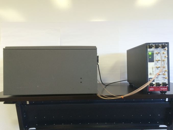
A few months ago, Ixia brought me into their offices to evaluate their WaveDevice system, which a Wi-Fi testing device uniquely suited to solving our testing needs. This system is effectively integrates a number of tools into a single chassis, including: Wi-Fi access points, traffic generators, programmable attenuators to set path loss, channel emulators to simulate a certain kind of RF environment in terms of interference and bandwidth, packet sniffers and analyzers, and signal/spectrum analyzers. These tools are implemented such that each layer of the Wi-Fi protocol can be analyzed, from the physical link layer of raw bits encoded at the carrier frequency of 2.4 of 5 GHz, to the application level where everything is neat bitstreams transmitted or received from specified addresses.
Of course, hardware is just one half of the equation. In order to provide a full solution, Ixia also has a full suite of software to make it possible to run common tests without spending excessive amounts of time developing custom tests. While WaveDevice supports custom tests through its API, WaveDevice out of the box supports a simple throughput test, which is effectively like iPerf but with more advanced statistics. There's also a general data plane test to evaluate throughput when varying the traffic direction, traffic type, frame size, and frame rate. Other than these basic tests, WaveDevice also has tests for rate vs range, roaming latency, and traffic mix testing. In the case of rate vs range, it's possible to run an automated sequence of throughput tests while varying frame rate, transmit power, and physical link rates. Meanwhile in the interesting case of roaming latency, we can test how long it takes for a Wi-Fi device to hop from one access point to another when fading out the signal of one access point and fading in the signal of another. Finally, the traffic mix test allows for a test of throughput when faced with competing traffic that is also transmitting.
Ixia has also made sure to support a range of OSes in order to make sure that almost any device can be tested against WaveDevice. In addition to maintaining iOS and Android applications, it seems that WaveAgent is a simple C application at its core that can be easily used for embedded systems like wearables and Wi-Fi cameras, so it seems that the "device" in WaveDevice really refers to any client with a Wi-Fi chipset.
While at first glance it might seem like these tests are pretty simple, it turns out that there's a huge amount of nuance to them. To try and understand the nuance I'm talking about, it's best to start with a basic primer on how Wi-Fi works.
Wi-Fi Basics: L1/PHY Layer
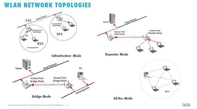
While most of our readers will have likely used Wi-Fi for the better part of two decades - and in my case it has essentially been around most of my life - in practice few people at all know that much about how Wi-Fi works, even within technical circles. Overall, Wi-Fi is a deceptively complex topic for those that are unaware of how it works, as it extends far beyond simple radio transmission principles, especially with the most recent iterations of the technology. Some knowledge can definitely be transferred over from LTE and other cellular technologies, but Wi-Fi is a very different technology in the sense that much of the intelligence has to stay on the device, as opposed to being supplied by a base station or access point. For the most part it’s up to the device to decide what the right physical link rate is based upon the RF environment, when to transmit data, how to roam between access points, how and when to use power save mechanisms, and to proper connection setup between the device and the access point.

Source: Wikipedia By Chetvorno - Own work, CC0
To understand Wi-Fi, we can start at the physical link layer, or Layer 1/L1. Anyone who has done some studying of how radios work will probably see a lot of similarities here as in general every Wi-Fi combo chipset that will ship in a phone is going to have a superheterodyne radio. At a high level, a superheterodyne radio is basically a radio that uses frequency mixing in order to convert the incoming signal to a different frequency to make the signal easier to process.
In the case of this kind of radio, the RF front end on the receive side contains filters, a low noise amplifier to get very weak signals up to usable levels, and a mixer is then used in conjunction with a local oscillator to get the incoming waveform from the signal frequency down to the carrier frequency. There are also likely to be some more filters and amplifiers after the local oscillator as the circuit is dealing with an electric signal (AC) at a much lower frequency, as while it’s pretty easy to get a transistor to switch on and off at 10 MHz it’s pretty much impossible to do the same thing at 60 GHz. From here, the signal can be converted from analog to digital, and also brought down to baseband frequency. For those that aren’t familiar with signal processing, baseband is effectively the frequency from 0 Hz up to the maximum signal frequency (which for Wi-Fi is often going to be the channel width, ranging from 20MHz to 80MHz). When the signal is at baseband, it’s possible to do a lot of signal processing that would otherwise not make a lot of sense, like Fourier transforms.
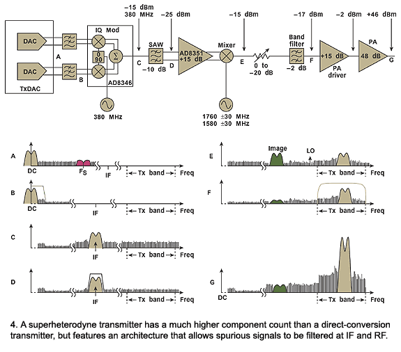
Source: Microwaves & RF
On the transmit side, Wi-Fi continues to look relatively similar at the physical block diagram level when compared to pretty much every commercial radio design since the 1940s. Starting at the modem, data is encoded from a digital bitstream into a baseband signal. This signal is then amplified appropriately, upconverted to the signal frequency with the local oscillator again. At this point we're back to the passband frequency that the radio will transmit at. Before the signal is transmitted though, it is fed through more amplifiers like a driver amplifier and filtered again. The signal is amplified again through the power amplifier to get up to a reasonable transmit power for the receiver before it is transmitted through the antenna.
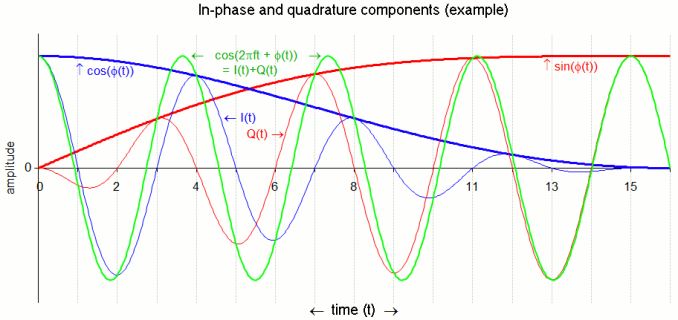
Source: Wikipedia, Bob K
This technically what enables the physical link layer to work, and any issues here can really cause everything to fall apart. In the case of 802.11ac physical layer, the signal is encoded into the carrier using modulation anywhere from BPSK up to 256QAM. We have discussed this before, but the short story is basically that a sinusoidal signal can be decomposed into two sinusoids that are out of phase by a quarter of a period.
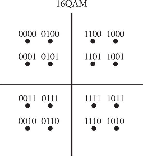
By varying these two components, it’s possible to generate an infinite number of points that represent a binary encoding. Of course, this is limited by the noise present in the received signal, which turns points into a probabilistic cloud.
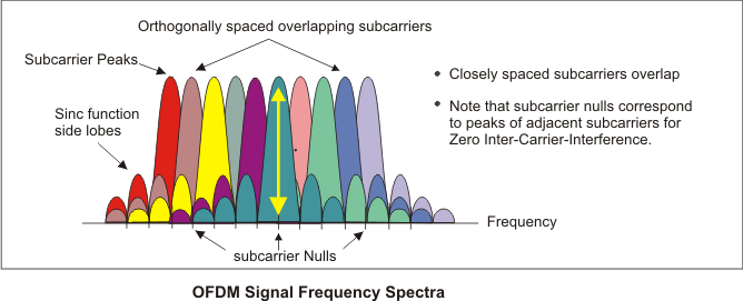
Source: Keysight Technologies
In addition to this varying of phase, Wi-Fi also splits the channel into narrow subcarriers to maximize throughput. This technique is known as orthogonal frequency-division multiplexing, and is used in a number of technologies like LTE as well.
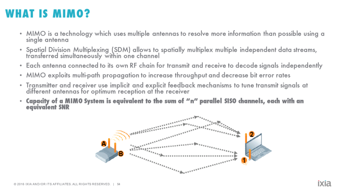
The other technique that is worth knowing about is Mulitiple Input and Multiple Output (MIMO) and Multi-User MIMO (MU-MIMO). In both cases, multiple antennas are used to enable additional throughput by utilizing multipath transmission. MU-MIMO in turn takes this a step further by using precise beamforming in order to spatially multiplex transmission and reception. While the concept is relatively simple, actually implementing this is difficult to say the least, which is why MU-MIMO Wi-Fi implementations have only been shipping for about a year or so.
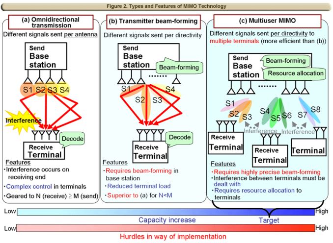
Source: 3G4G Blog, NTT
This aspect of Wi-Fi is known as the Physical Medium-Dependent layer, or PMD layer. There are more aspects that could be discussed regarding the physical link layer, but in the interest of not making things any more confusing we’ll stop here and talk about what aspects of the physical layer WaveDevice is actually capable of testing. With every packet, WaveDevice is capable of reporting a number of statistics about what’s happening at the physical link layer. Importantly, this includes the constellation error, by showing the average magnitude of the deviation of the actual I/Q position relative to the theoretical I/Q position for a given encoding. It’s also possible to look at how well the device is constraining its transmission to specific bands/channels, and whether the device is transmitting excessive levels of power, although transmit power limits is really more the realm of FCC compliance than anything else.
As a result, when we’re looking at relative Wi-Fi performance, we can actually start to make determinations about whether the problem with a device’s Wi-Fi performance is because it’s just not transmitting data properly and causing data corruption, or if it’s something happening at the software level. While the physical layer is critical, if you subscribe to the OSI model of networking then there are six layers above it that need to work as well to make sure that your cat pictures load as they should. So next we'll take a look at the data link layer to better understand how Wi-Fi works and what WaveDevice is capable of testing there.
Wi-Fi Basics: L2/MAC Layer
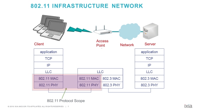
The next layer up in OSI model is the data link layer, which helps to encapsulate raw bits into something more manageable. The key to understanding this subject (and many other technology concepts) is seeing everything in layers of abstraction, because otherwise it would be incredibly difficult to talk about and analyze aspects of electronics without getting lost in an excess of mostly irrelevant information.
In the case of Wi-Fi, the MAC layer, which is within the OSI data link layer, is where a ton of the intelligence resides on the device (this in particular setting it apart from LTE). At its most basic form, the MAC layer hides the reality of the physical link layer with an abstracted network. To the parts of the networking stack operating above the MAC layer, the network appears to be solely composed of endpoints. Furthermore this abstract network appears to be full duplex, which means that data can be received and transmitted simultaneously.
Obviously, infrastructure-mode Wi-Fi isn’t solely composed of endpoints, and neither is Wi-Fi full duplex. Rather, due to the nature of how radios work, Wi-Fi is half duplex (radios can only talk or receive), as trying to transmit in full-duplex mode results in self-interference due to the receiver picking up the signal from the transmitter. There’s actually a significant amount of research going into solving the duplex problem to improve data rates and spectral efficiency, but from a commercial perspective most consumer devices don’t have this kind of technology yet.
In order to enable this kind of abstraction, there are a lot of systems in place in the Wi-Fi standard. While it might be relatively simple to abstract away the fact that the network actually has an access point that routes communications from one endpoint to another, but emulating full-duplex communication in a half-duplex medium is surprisingly complex. In general, only one device on the access point/spectrum can transmit at any given time, and if this rule is broken you end up with a lot of interference effects and whatever data was being transmitted is pretty much as good as lost. However it should be noted that there is an exception here with the latest generation devices supporting MU-MIMO, where multiple antennas are used to create areas of constructive and destructive interference so that “beams” are created to allow for multiple simultaneous transmissions.
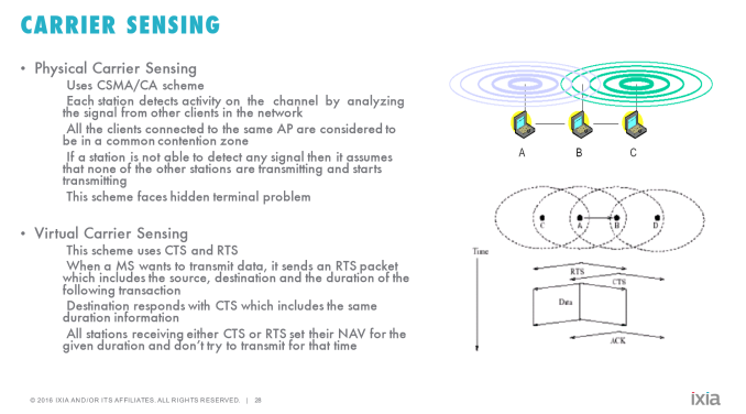
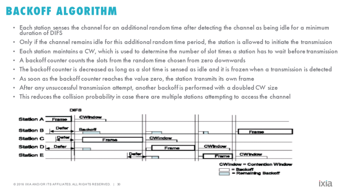
As a result of these limitations, the MAC layer has to require that both devices and access points cooperate in sharing the spectrum using a time division scheme known as Carrier Sense Multiple Access with Collision Avoidance, or CSMA/CA. Devices connected to the AP have to make sure to listen to the channel with a receiver to first verify that the channel is clear, then can transmit data by first sending a request to send packet and waiting for a clear to send packet. Once the clear to send is received, the device can transmit its data. Because there’s no guarantee here that some other device didn’t also simultaneously transmit, the device has to listen for an acknowledgement by the access point that the data was received. If an ack is not received by a certain period of time, the device has to assume that someone else was also attempting to transmit and respond by backing off on transmissions for a specified period of time before transmitting again.
WaveDevice in turn is actually able to specifically test this part of the MAC layer using its ecosystem performance test, in which clients are simulated by WaveDevice and the device of interest is tested to see whether its CSMA/CA algorithms are designed so that appropriate throughput levels are maintained in the face of competing traffic. It turns out that some devices can be too aggressive and collide with other traffic, or too passive and spend too much time backing off. Getting too far from ideal in either direction will seriously affect throughput, so from a validation standpoint this is a test that is of interest as soon as you’re in environments like a convention center or press conference where there may be hundreds, if not thousands of other devices in the vicinity all on the same few channels.
Another part of the MAC layer that is important to understand for the purposes of Wi-Fi testing is rate adaptation. While WaveDevice allows for manual control of the Modulation and Coding Scheme (MCS) used by the device in addition to the number of spatial streams for MIMO and other settings like guard interval and channel bandwidth, it’s important that a device selects all of these things automatically and correctly. This is necessary in order to ensure that packet loss and retransmission isn’t happening at excessive rates in higher parts of the networking stack and that throughput at higher layers is maximized. Importantly, unlike the cellular world, Wi-Fi lacks channel quality indicators that allow for the device and access point to directly determine what the ideal modulation and encoding scheme is. This means that rate adaptation has to happen based upon factors like packet/frame loss rates.
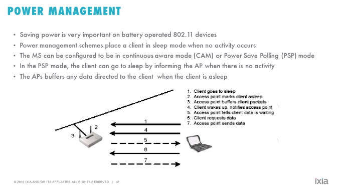
Meanwhile it’s also important for the device to avoid transmitting signals at excessive power levels, as power consumed by the power amplifier directly affects battery life. Given that power amplifiers generally have a power-added efficiency of somewhere around 40% in modern mobile devices, it’s not entirely surprising to have a power amplifier consume somewhere around 1W of power alone, even before considering other parts of the RF chain or the rest of the device. Using a real world example here, our web browsing battery life test is long enough that even an average difference of 200 mW can cause a runtime difference measured in hours, so proper control of transmit power is definitely important. It's also important for the Wi-Fi chain to go to appropriate sleep states in order to save power. When implemented improperly, there can be some pretty serious knock-on effects in terms of idle battery life because unnecessary wake-ups can lead to waking the main CPU, which is relatively enormous in terms of power consumption on a mobile device.
From a testing perspective, these aspects can also be tested on WaveDevice by looking at how a device performs by testing for throughput while steadily decreasing transmit power on the access point. This rate vs range test can also be a test of the RF front end/physical layer, though it requires that the test chamber is set up properly to ensure that the device receives a constant transmit power and multipath propagation regardless of angle to avoid issues with anisotropy (in the real world, devices vary in their transmit and receive capabilities based on their angle and orientation). This test also allows for direct measurement of the ability of a device’s Wi-Fi chipset to demodulate and decode the signal in the face of decreasing SNR and received power, in addition to its ability to select the ideal MCS rate to maximum throughput and reduce packet loss.
Wi-Fi Performance: iPad Pro and Pixel C
Now that we’ve gone over the basics of how Wi-Fi works, we can get to the true focus of today's article: the results. As this article is something of a preview of what we're working on behind the scenes, I’m still figuring out how I want to condense and present these results for future articles, so for now we’ll be looking at raw data generated from WaveDevice software. As you might be able to guess, it turns out that there are a number of differences in Wi-Fi performance that are readily apparent once you start running tests using WaveDevice.
In the interest of setting a baseline for performance, I elected to compare two tablets that I had on hand that could run WaveAgent software. Apple's 12.9" iPad Pro uses a BCM4355 solution with 2x2 802.11ac, while Google's Pixel C uses a 2x2 802.11ac device. Judging by the system firmware of the Pixel C it looks like we’re looking at BCM4350 chip, so at a high level there really shouldn’t be a huge delta between the iPad Pro and Pixel C.
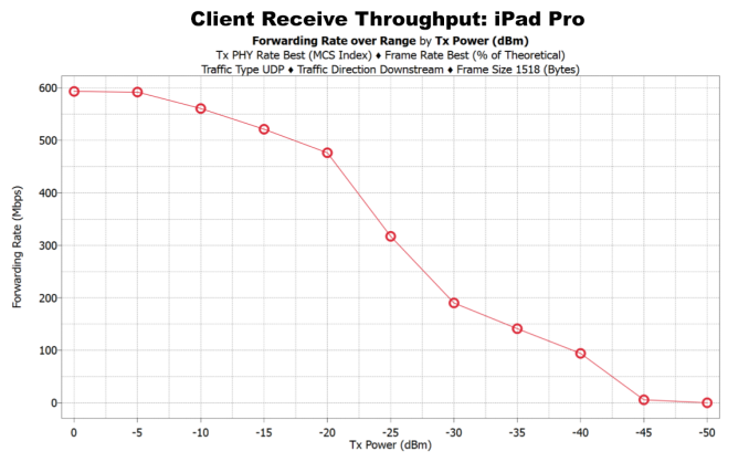
To start off we can look at the range vs rate test, which is designed to see how the device performs in response to fading base station transmit power. In the case of the iPad Pro, at 15 dBm transmit power the device reported -33 dBm RSSI (received signal strength indicator). It's important to note that the IEEE 802.11 standard doesn't really define RSSI beyond a unitless value, but in the cases we're interested in RSSI is really more a reference to received power, where dBm is the unit of power rather than watts due to the huge differences in power from good to poor reception. However, in the interest of focusing on the rate at which throughput decreases the test sweep in transmit power was 0 dBm to -50 dBm with a 5 dBm step. With this sort of data, we can actually see the kind of throughput that the device sustains for a given RSSI level and for a given transmit power. Of course, there are a number of other statistics that can be examined here as previously discussed, but basically the main takeaway is that the iPad Pro is capable of sustaining 600 Mbps and approaches 0 Mbps at -45 dBm transmit power. Given that we’re looking at a ~47 dB path loss from the transmitter to the receiver, this basically means that the iPad Pro is capable of sustaining non-zero throughput all the way out to roughly -90-95 dBm RSSI.
If you think back to the explanation of the physical layer of Wi-Fi, the reason why this is important is because received power is not quite the same thing as signal to noise ratio. While having high received power does improve your signal to noise ratio, if your receiver has a great deal of phase noise to begin with from poor amplifier design or some other issue in the chain, your throughput is going to fall flat even if the device can transmit/receive effectively to/from the access point.
For the Pixel C, things aren't quite as rosy. In this case I recorded a -43 dBm RSSI at 15 dBm, which is already quite concerning to start with. I attempt to maximize RSSI and throughput in my tests, so it's likely that the Pixel C either has a highly directional antenna, insufficient antenna gain, or a significant impedance mismatch somewhere leading to significant signal reflection. These are all unquestionably hardware problems that are unlikely to be solved by any software changes. The Pixel C is also highly unstable as it approaches the edge of reception, so the test above stops at -30 dBm transmit power because attempting to go to -35 or -40 dBm resulted in the device disconnecting from the network. Resolving this required restarting WaveAgent, WaveDevice, and deleting all saved SSIDs from the Pixel C. I also had to change the SSID of the test AP, so to have any usable results at all it was necessary to adjust the test parameters for the Pixel C.
Putting these issues aside, it's obvious that the Pixel C is underperforming here regardless of how we go about it. Maximum throughput is well below what the iPad Pro can achieve even at short ranges, and the same is true even when compensating for the delta in RSSI. -30 dBm transmit power on the Google Pixel C is equal to -40 dBm transmit power for the iPad Pro when equalizing RSSI, so the iPad Pro can sustain roughly 50% higher throughput even at the extremes of reception. Equalizing RSSI means that we're still ignoring the antenna and other portions of the RF front-end, so it's entirely possible that the delta is even worse given that I couldn't achieve anywhere near -30 dBm RSSI on the Google Pixel C regardless of device orientation within the RF isolation chamber.
As mentioned previously, WaveDevice actually allows for a deeper look at what’s going on behind higher-level failures. Out of curiosity, I decided to run a simple upload throughput test at 15 dBm transmit power at the Pixel C’s highest possible throughput rate, and I found that it’s basically unable to use the highest throughput 256 QAM because there’s too much noise between each point on the constellation to tell what the device intended to transmit. Even when it can use MCS 9 (256 QAM and only 1 redundant bit) the Pixel C averages roughly a 3-4% EVM error, while the iPad Pro was closer to 1-2% at 256 QAM. And though 3-4% might sound like a small value, 256 QAM leaves very little room for error. I regularly saw drops down to MCS 7 (64 QAM, 1 redundant bit) even in ideal cases which resulted in noticeable drops in throughput during this simple test. I'm hesitant to go any further in the analysis here since we don't know enough about the design of the Pixel C's Wi-Fi subsystem, but an OEM would be able to use this information to start searching for potential sources of phase noise. It may be that we're looking at something like improper impedance matching somewhere in the system, amplifiers that are either poorly selected or poorly integrated, and/or a phase-locked loop somewhere that isn’t set up or designed properly for this task.
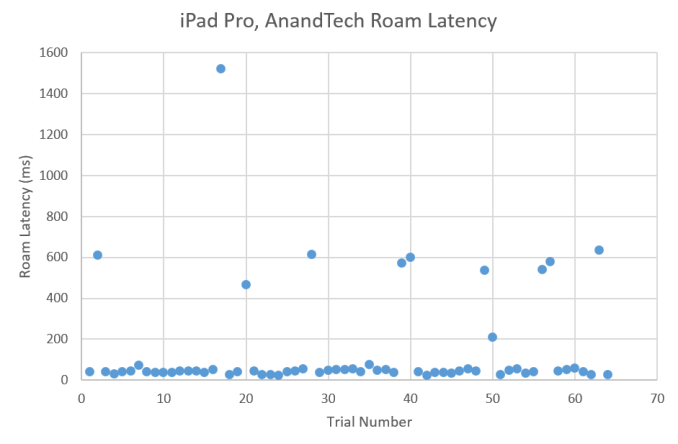
Moving on to the next test of interest, we can take a look at how these two devices perform in our roaming test. While I'm still experimenting with this for use in full reviews, for now I set up a test with a 10 Mbps load and a starting transmit power of 10 dBm, going down to -40 dBm for the noise floor with a 3 dBm step every second. 64 access points are used for this test, and all of them are on the same channel which should make this easier as the device doesn’t need to scan on all channels for the next access point to jump to. This is a fairly aggressive test, as I’ve run this test on a few devices and nothing is 100% perfect here, although some devices are clearly better than others.
In the case of the iPad Pro, we see a median roam delay of 42ms, which is reasonably respectable given the 10 Mbps traffic and fairly aggressive transmit power changes. However, the Google Pixel C seriously falls short here despite using a similar Wi-Fi chipset as I encountered a number of times when the Pixel C dropped from the network entirely and was unable to complete the test. Even when it didn’t fall off the network, the median roam delay was 682ms, which is pretty much guaranteed to result in some kind of disruption to things like VOIP calls, video conferencing, and similar problems. Ultimately the issue here is that roaming is a very common scenario a device will need to handle, as any office, school, or convention center is pretty much guaranteed to have multiple access points with the same SSID and authentication. There’s also the strong possibility that each access point is on a different channel, which would only increase roam latency figures relative to what I was able to test.
Needless to say, WaveDevice is an incredibly powerful system when it comes to providing insight into parts of Wi-Fi that have effects at the user experience level. Observant readers might have noticed that there's no Traffic Mix test here, and it turns out that the two devices we're looking at don't have particular issues with the Traffic Mix test. However, given the data shared with Ixia on devices they've tested, it's likely that the need for Traffic Mix testing will appear sooner rather than later. For full reviews we'll be including this test as well for completeness.
Closing Thoughts
As mentioned in the introduction, we've always been faced with the problem of seeing subjective differences in RF performance between devices, but lacking the data and repeatable tests to back it up. In my time at AnandTech, I've always been working to try and improve our reviews, and RF testing has been one of the major areas where I've sought to improve our reviews and benchmarks. While we've had some basic tests, we've never gone into this area with the same level of depth and breadth that we have with many other components of the stack. As connectivity is probably the most important thing in computing, it was evident that we had to tackle this subject at some point.
Our first leap into this area is the addition of Ixia's WaveDevice to our test suite. From the start, this system was conceived as an all-in-one chassis that could give data to prove or disprove subjective observation, to bring repeatable testing to seemingly one-off edge cases, and to do so at scale for Wi-Fi. It turns out that this system is quite powerful, and can show how a device performs in tests that directly correlate with user experience. These tests include throughput with respect to range, roaming latency, and ecosystem performance. The rate versus range test shows the quality of the RF front-end and the ability for the modem to properly decode and encode data in the face of decreasing SNR. The roaming latency test shows how well a device can detect and react to changing reception conditions. The ecosystem performance test can show how well a device can acquire the channel without conflicting with other traffic.
In the case of the iPad Pro and Pixel C, we found that WaveDevice was able to show a number of notable interesting data points from both an end user perspective and an engineering perspective. With the rate vs range test, it was possible to clearly see how well a device would perform in response to worsening reception from a user experience perspective. From an engineering perspective, it was possible to identify the root cause for the Google Pixel C’s poor Wi-Fi performance by using WaveAnalyze and an RF analysis blade in WaveDevice. While determining the root cause is still beyond what we can do with limited information on the hardware, an OEM would be able to act on the information provided by WaveDevice to improve their product before it reaches mass production.
In addition to the rate vs range test, the roaming latency test was quite illuminating. While root cause analysis is more difficult and best left to actual engineers, it’s quite obvious that the iPad Pro passed this test with flying colors while the Pixel C shows some serious deficiencies. If you regularly encounter large Wi-Fi networks with multiple access points all under a single SSID/name like eduroam, it’s obvious that the Pixel C will be an exercise in frustration if you’re hoping to keep a working Wi-Fi connection on the move. Even when the device roams successfully, the time that the device spends moving from one access point to the next is long enough on average to result in noticeable connection interruptions. When it doesn’t roam successfully, it seems to get stuck on a single access point and basically drops off the network entirely without manual intervention or has to re-authenticate and acquire a new IP address, which is guaranteed to cause most traffic to be dropped.
Of course, while this data is interesting, it's not very helpful without an understanding of how Wi-Fi works. Starting from the physical link layer, pretty much every modern radio in a mobile device is going to have a superheterodyne radio architecture, which uses an intermediate frequency before stepping down to a baseband frequency that allows for better signal processing. There’s a lot of bits and pieces here, but the key component here is the local oscillator that allows for successive stages where a baseband signal is encoded into a carrier or decoding a carrier to the baseband signal. Everything else is basically a lot of complicated circuits that are designed to help tune the RF circuits to oscillate at the correct frequencies and to boost a signal’s power multiple orders of magnitude from its baseband state.
With this radio as the foundation, we can then focus on modulation and coding schemes. Wi-Fi uses two primary methods of maximizing throughput as close to the Shannon limit as possible. These two methods are known as Quadrature Amplitude Modulation (QAM) and Orthogonal Frequency Division Multiplexing (OFDM). OFDM is basically a method of slicing up spectrum into small subcarriers. When done correctly, there are a number of benefits from a design perspective like simpler radio design, high spectral efficiency, simpler signal processing algorithms, and improved interference immunity.
If you can think of OFDM as slices of frequency, QAM is used on each slice of frequency. By using phase variation and amplitude variation, it becomes possible to represent multiple bits with a single frequency slice. In the case of Wi-Fi and LTE, we’re looking at up to 8 bits per “slice”, which means that there are 256 potential combinations of phase and amplitude to consider. However, noise limits the ability for a receiver or transmitter to differentiate between these combinations, so depending upon the channel conditions it may be necessary to increase the difference between each state to avoid data corruption.
The final method worth noting that can improve performance is MIMO. At its heart, MIMO is a form of parallelism to improve bandwidth and/or range. By exploiting the fact that signals will often have multiple propagation paths, it becomes possible to use these multiple paths to send multiple streams of data simultaneously. When taken to its logical conclusion of MU-MIMO, it’s possible to see additional throughput advantages as the device and access point can utilize beamforming to focus transmissions to reach a specific location rather than transmitting in all directions.
All of these aspects taken together form the physical link layer, which is best understood as the base hardware mechanics. The next layer up is the data link layer. This layer is used to help abstract away the underlying mechanics of all networking technologies so that the layers further up the networking stack don’t have to be tailored towards any one type of network technology. For the purposes of our reviews and understanding Wi-Fi, the key area of interest here is the method used to emulate a full-duplex network with a half-duplex technology. Full duplex in this case means simultaneous transmission and reception, while half-duplex only allows for transmission or reception, not both at the same time.
In the case of Wi-Fi, this emulation method is known as Carrier Sense Multiple Access with Collision Avoidance, or CSMA/CA. At a high level, devices listen to the channel to wait until it’s clear before sending the access point a request to send, at which point the access point must respond with a clear to send before the device can transmit on the channel.
In addition to multiplexing, the MAC layer determines how to control the physical link layer, which includes selection of modulation and coding schemes and power management of the radio. Due to the nature of Wi-Fi, the device has to use a number of heuristics to determine what kind of power save mechanisms and link rates to use rather than specific algorithms like traditional cellular networks. Of course, the MAC layer is also needed to determine how to route traffic and to transparently handle errors or corruption, but this is beyond the scope of this article.
Overall, reaching the level of understanding with regard to theory and practice has been one of the biggest undertakings that we’ve ever had at AnandTech. As I mentioned earlier, wireless testing has been one of the major frontiers that we’ve yet to fully explore. It turns out that digital logic and computer science don’t help much with understanding RF, and as a result something that might have seemed simple from our iPerf tests has exploded into months of research and experimentation. I’d like to thank Ixia for providing their significant expertise and equipment. More importantly, I’d like to thank all of our readers that have really provided the drive to make all of this possible. I look forward to seeing what we couldn’t see before.

