Original Link: https://www.anandtech.com/show/6231/gigabyte-x79sup5-wifi-review-ultra-durable-5-meets-the-c606-chipset
Gigabyte X79S-UP5 WiFi Review: Ultra Durable 5 Meets the C606 Chipset
by Ian Cutress on September 6, 2012 6:36 PM EST- Posted in
- Gigabyte
- Motherboards
- X79
- C606
As part of the Computex 2012 show, Gigabyte demonstrated to us their new version of Ultra Durable. This fifth iteration of their power delivery combines their previous features with a new phase from International Rectifier, which is marketed to offer up to a 60°C lower temperature than traditional MOSFET solutions. Initially this new design is being paired with six motherboards, all designated with UP rather than UD in the name. The first of these we have in is the X79S-UP5 WiFi, which combines Ultra Durable 5 with the C606 chipset. The C606 chipset is the server version of the X79 chipset, which enables up to eight SAS ports.
Ultra Durable 5 and IR3550 PowIRstage ICs
Gigabyte’s Ultra Durable branding is one of a myriad of features it likes to use in advertising its products. The Ultra Durable system allows Gigabyte to continually add new features to its power delivery, with the latest being the addition of new IR3550 PowIRstage ICs.
By combining many elements of the power delivery process into one device, we save real estate on the board – combine this with some IP from International Rectifier regarding packaging and internal structures, and Gigabyte states we have many of the following benefits:
- Each phase offering up to 60A, thus less phases are needed (reduces power consumption)
- Efficiency of up to 95%, also decreasing power consumption
- Up to 60°C cooler than traditional MOSFET solutions, and 20°C cooler than Ultra Durable 4.
Let us put this into perspective – normally combining elements into a smaller area causes problems for heat production, but this solution has been designed to get around it. Power delivery, for the large part of consumers, is either something that works or does not. Inherent in the design is the longevity, but it rarely ever becomes a major feature that sways a purchase decision. Whether it is digital or analogue, the vast majority of users do not know, let alone care.
The major push with Ultra Durable 5 is the temperatures. “Up to 60°C cooler than traditional solutions” is part of the Gigabyte PR machine. The scenario to produce these claims could be a common one in many of our readers homes - in small systems using all-in-one liquid coolers (Corsair, Kühler), where air flow is not a major part of the build, and heat lingers inside the case. The design of the IR3550 is such that the heat is dissipated, and designed not to affect the system as. This has an appreciative affect on motherboard choices for low noise, low airflow situations.
The other issue, which will hit all users, is the cost of implementing such a technology. It does not come cheap. While at Computex, I was quoted that for the high-end motherboards that will initially use these ICs, the power delivery sub-system alone can cost as much as a low-end consumer motherboard. That means on designs such as the X79S-UP5, the power delivery section could cost as much as $80 of the boards overall cost to build.
The use of IR3550 ICs from International Rectifier is not an exclusive deal between IR and Gigabyte. Other companies are free to jump in with IR if they want to use this technology. In order for it to be cost effective though, we need them all to jump in to drive the cost down. Then when we see the ICs on ITX sized boards, they will be extremely useful.
Initially Gigabyte has six motherboards using the new Ultra Durable 5 system. The boards that do are designated UP, as in the Z77X-UP4, rather than UD, which is Ultra Durable 4. With that, let us get to testing the X79S-UP5 WiFi.
Gigabyte X79S-UP5 WiFi Overview
Despite the name of this board containing ‘X79’, the chipset commonly associated with Sandy Bridge-E processors and Socket 2011, the addition of the ‘S’ motive indicates this board uses one of the server versions of the chipset. Gigabyte had four to chose from – C602, C604, C606 and C608, each increasing in features and cost. As quoted from the Intel website, “These chipsets offer many of the capabilities of the Intel® C200 series chipsets with additional support for enterprise storage and additional I/O bandwidth to address highly demanding enterprise workloads.” Specifically this link will demonstrate the exact differences between the chipsets, but the server C60x all follow the same chipset diagram (for a dual processor system):
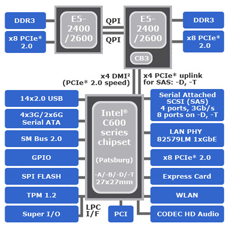
We also get PCIe lanes for PCIe devices. In the X79S-UP5 WiFi, Gigabyte has decided to use the C606 chipset - this gives Gigabyte leeway to include full Xeon support, as well as ECC memory (with a Xeon processor), and an extra eight SAS / SATA ports onboard.
The X79S-UP5 is marketed as a board for workstations, for enthusiasts who would rather build their own number crunching machine than buy one. By including the IR3550 in the power delivery, Xeon support, ECC support and SAS through a server chipset, Gigabyte are trying to cover as much as possible before going beyond to a dual processor system, like the GA-7PESH1.
The main competition for the Gigabyte X79S-UP5 comes from the ASRock X79 Extreme11, although these two motherboards are in completely different price brackets ($330 vs. $600 MSRP), and as such the ASRock has clout with two PLX chips and an LSI chip while still retaining the X79 credentials. So while the X79S-UP5 is ‘only’ limited to three-way GPUs at x16/x16/x8, and SAS 3 Gbps ports, it does offer a choice for the more price-conscious workstation, especially with the power delivery.
In our testing, we used an i7-3960X in order to keep our benchmarks consistent with X79 motherboards, and given the recent debate regarding MultiCore Enhancement (MCE), we can confirm that the Gigabyte X79S-UP5 WiFi enables MCE when XMP is enabled. As a result, we expect the Gigabyte to match the ASUS ROG boards in our testing suite – in fact, it often beats our ROG products due to some aggressive switching algorithms implemented on board. Unfortunately, I can confirm that MCE does not enable for Xeon processors.
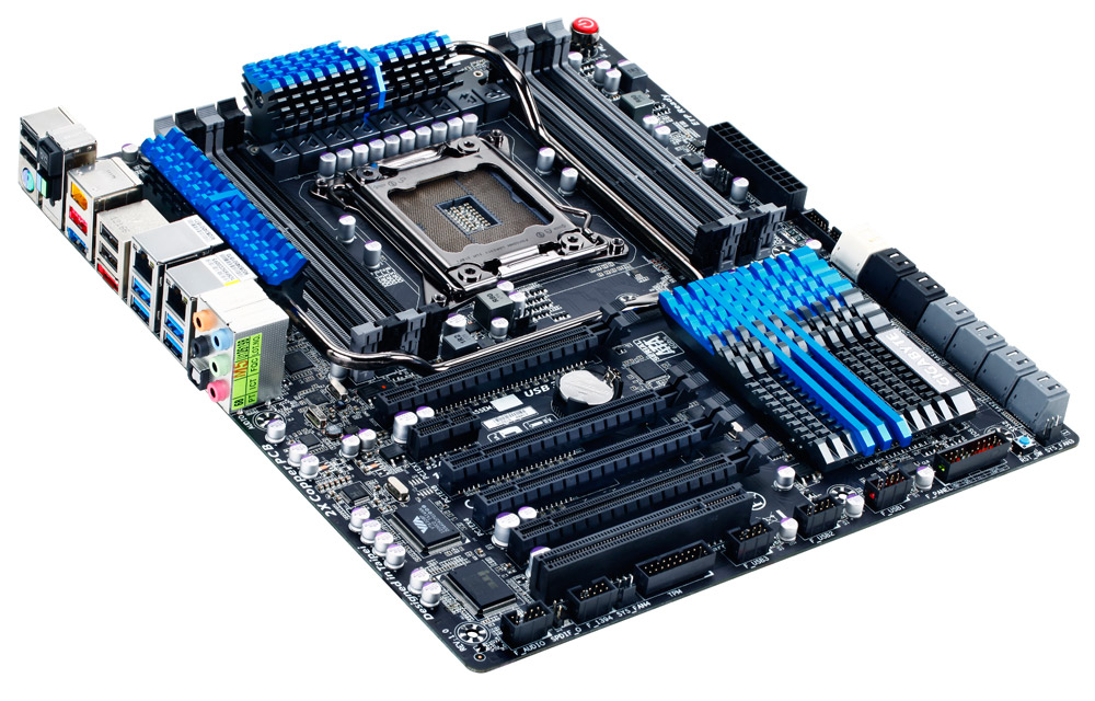
Visual Inspection
The X79S-UP5 WiFi adheres to the loosely defined E-ATX board size – for most users that means that the board is an extra inch wider than normal ATX sized boards, but that allows Gigabyte to place connectors right on the edge given that real estate can be a premium. For an upper workstation board, Gigabyte has gone with a blue and black theme on the heatsinks combined with a black and grey for memory and most of the SATA ports.

The socket area is normal for an X79 motherboard – we have the memory to the right and left, and a heatsink to the top. The heatsink is kept low (~26mm from the PCB base), but with the heatpipe in play some large square air coolers could be restrictive, possibly requiring low profile memory. I believe the main intention is for this board is to be paired with an all-in-one liquid water cooler such as a H80 or 920 to keep it simple. The heatsinks themselves are located above the socket, to the left of the memory, and on the chipset itself. In order to maximize the heat removal, all three heatsinks are connected via a heatpipe, and thus there is no need for an extra chipset fan.
For fan control around the motherboard, we have a 4-pin CPU fan header below the socket, a 4-pin SYS fan header to the top right of the memory, and another 4-pin SYS header next to the 24-pin ATX power connector. The other two headers on board are 3-pin SYS headers at the bottom end. Personally, I think one of these could have been moved to next to the CPU fan header, just to promote the situation where more CPU fan headers are provided.
Along the right hand side of the board, we get a big red power button for enthusiasts, our standard 24-pin ATX power connector with a 4-pin fan header beside it, a USB 3.0 header, and the SATA ports. Starting with the USB 3.0 header, this is powered by a Fresco USB 3.0 Controller (the FL1009). I cannot say if I have ever seen this brand of USB 3.0 controller on a top line motherboard - it means the USB 3.0 controller market has several players in the form of ASMedia, Etron, Via, Renesas (NEC), Texas Instruments and Fresco.
Gigabyte has decided to use all the chipset SATA ports alongside the SAS enabled ports provided by the C606 chipset. From top to bottom, we have two SATA 6 Gbps in white, four SATA 3 Gbps in black and the eight SAS ports in grey, with these SAS ports also supporting SATA devices at 3 Gbps. After some internal discussion with Gigabyte, I tested these SAS ports with SATA drives in RAID-0, but the peak speed was topping out at under 1.0 GBps for sequential reads and writes, despite the theoretical maximum being ~2.4 GBps (300 MBps x 8). A bit of checking later and it turns out that Intel specifications limit the bus speed between the SAS ports and the chipset at PCIe 1.0 to ensure data integrity. Gigabyte in turn released a beta BIOS (F3a) which enables users to select PCIe 1.0, 2.0 or 3.0 for their SAS ports. This increases the peak throughput when drives are placed in RAID-0 to 1.8 GBps at PCIe 2.0 and 2.39 GBps at PCIe 3.0:
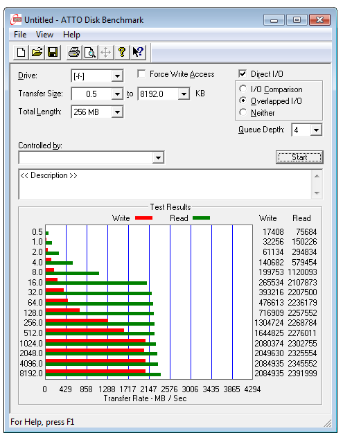
Eight SATA drives in RAID-0 set at PCIe 3.0
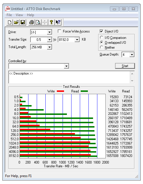
Eight SATA drives in RAID-0 set at PCIe 2.0
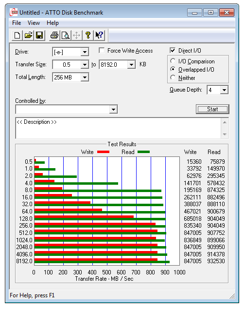
Eight SATA drives in RAID-0 set at PCIe 1.0
As stated with the ASRock X79 Extreme11 though, eight-way RAID-0 is an obscure usage scenario. Like with the ASRock X79 Extreme11, the SAS ports on the Gigabyte X79S-UP5 WiFi can only perform RAID 0, 1 and 10, though this time it is due to Intel specifications. If Intel had rigged the ports for RAID 5 or RAID 6, I feel a lot more of the user base would be available.
Also on the right side of the motherboard we have two soldered on BIOS chips for Gigabyte's dual BIOS functionality. In order to switch between these two BIOSes, the button is on the IO panel and shifts blue and green depending on which BIOS is in use.
On the south side of the board Gigabyte have included their usual array of headers, including a Trusted Platform Module header (makes more sense in a workstation environment), an IEEE1394 header, three USB 2.0 headers, audio/front panel headers and a reset switch. All we are missing here is a ClearCMOS button (which actually is on the IO panel, so nothing lost there), but more importantly I like to see a two-digit debug LED on board. There are arguments against the Debug LED for sure - namely that there is no use for it when a product is inside a case. However, from my perspective, the Debug LED feature gives me peace of mind when the board is booting, and if it ever produces a POST error, the Debug LED gives a code number that helps in diagnosis. In reviewing, it aids in overclock testing or memory debugging if there is a memory issue.
Due to Gigabyte applying the heatsinks in the way that they have, the PCIe layout is based on six ports overall, aimed at a maximum of a three GPU setup. From top to bottom, we have an x16, x1, x8, x4 (from the chipset), x16, and a PCI. This means dual GPU + sound card + WiFi setups are catered for, or any combination therein. As the focus is on workstation scenarios, we could easily put in a Quadro and a pair of Tesla GPUs, or one of each and a dedicated single slot video output card and the included WiFi module.
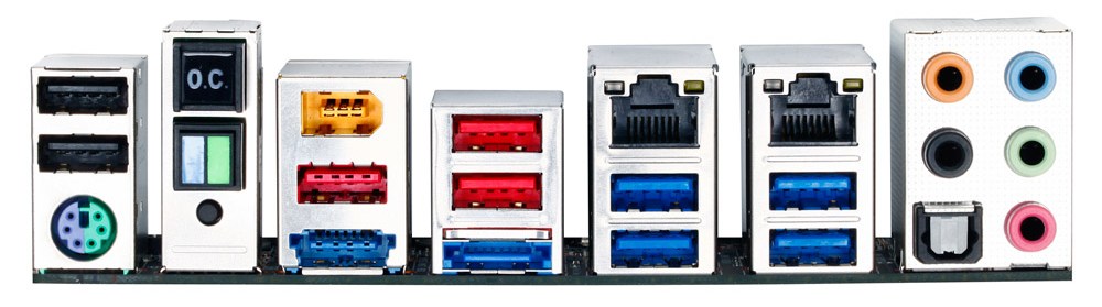
From left to right on the IO panel we have two USB 2.0 ports (black), a combination PS/2 port, an OC Button (detailed later in the review), a BIOS Switch, a ClearCMOS, an IEEE1394 port, a USB 2.0 port, a combination USB/eSATA port, two more USB 2.0 ports, another eSATA port, dual gigabit Ethernet (one Intel, one Realtek), four USB 3.0 ports (VIA controller), optical SPDIF output and audio jacks.
Board Features
| Gigabyte X79S-UP5 WiFi | |
| Price | Link to Newegg |
| Size | ATX |
| CPU Interface | LGA2011 |
| Chipset | Intel C606 |
| Power Delivery |
Intel Second Generation Core i7 Sandy Bridge E Intel Xeon E5-16xx and E5-26xx |
| Memory Slots |
Eight DDR3 DIMM slots supporting up to 64 GB Up to Quad Channel DDR3, 1066-2133 MHz Supports ECC, un-buffered memory with Xeon Processors |
| Onboard LAN |
1x Intel 1x Realtek |
| Onboard Audio | Realtek ALC898 |
| Expansion Slots |
2x PCIe 3.0 x16 1x PCIe 3.0 x8 1x PCIe 3.0 x4 1x PCIe 2.0 x1 1x PCI |
| Onboard SATA/RAID |
2x SATA 6 Gbps (Intel), RAID 0, 1, 5 and 10 4x SATA 3 Gbps (Intel), RAID 0, 1, 5 and 10 8x SAS 3 Gbps (C606), RAID 0, 1 and 10 Note - SAS uplink by default is PCIe 1.0. BIOS F3a or above needed to adjust above 950 MBps total. |
| USB |
12x USB 2.0 Ports (Intel) [6 back panel, 6 onboard] 4x USB 3.0 Ports (VIA VL800) [4 back panel] 2x USB 3.0 Ports (Fresco FL1009) [2 onboard] |
| Onboard |
2x SATA 6 Gbps 4x SATA 3 Gbps 8x SAS 3 Gbps / SATA 3 Gbps 3x USB 2.0 Headers 1x USB 3.0 Header 1x IEEE 1394 Header 5x Fan Headers 1x ClearCMOS Jumper Power/Reset Buttons TPM Header |
| Power Connectors |
1x 24-pin ATX Power Connector 1x 8-pin CPU Power Connector |
| Fan Headers |
1x CPU (4-pin) 4x CHA (two 4-pin, two 3-pin) |
| IO Panel |
1x Combination PS/2 Port 1x CPU OC Button 1x BIOS Switch Button 1x ClearCMOS Button 1x IEEE1394a Port 4x USB 3.0 Ports 5x USB 2.0 Ports 1x eSATA/USB Combination Port 1x eSATA Port 1x Intel GbE 1x Realtek GbE 1x Optical SPDIF Output Audio Jacks |
| Warranty Period | 3 Years |
| Product Page | Link |
Gigabyte has aimed to give this board a lot - the C606 chipset enables those SAS ports but we also have the new power delivery system. Combine this with dual NIC, bundled in WiFi card, some legacy ports, a TPM module, six USB 3.0 ports and five fan headers. There is not much else to add component wise. What I will say is that the chips that add the IEEE1394 ports and SuperIO on the bottom of the board (Via and iTE) are quite large. I wonder how many people still would require IEEE1394 and PS/2 on a workstation board - the option could be to do what is on the UP5, or make the space available for a mini-PCIe port and put the WiFi card in there.
Gigabyte X79S-UP5 WiFi BIOS
Despite the fact that Gigabyte were late to the graphical BIOS party back in the P67 era, today we have a fully functioning BIOS on our hands to play with. Over time, it has increased in speed, usability and presentation. The overriding message, as with any graphical BIOS, is to expose the nature of the configurable settings in an aesthetically pleasing way. If you can get around the fact that Gigabyte calls a 2D image the '3D BIOS' technology, then usually the Gigabyte BIOS is an easy one to navigate and use.
Since the inception, Gigabyte seems to have gone through three phases of BIOS. The first was slow and clunky, with transitions taking time. The second saw the system speeded up, but in order to type numbers in NumLock had to be pressed which caused a 10-second delay. Later BIOSes removed this time penalty, and this is what we see on the Z77 platform. However there still seems to be an issue with the C606 chipset and that NumLock feature, as it is still a problem on the F3a BIOS for the X79S-UP5 WiFi. Also of note is our Deferred Procedure Call latency testing, which determines how well requests for CPU time are dealt (critical for audio processing) - sometimes the software in the OS can have a negative impact, such as EasyTune 6, due to their system monitoring feature. Gigabyte have solved the issue on Z77 with a BIOS update, however it still lingers here in C606.
Regarding MultiCore Enhancement, the X79S-UP5 does include MCE as part of the setup when XMP is enabled. I can confirm this for regular socket 2011 Core processors, however I can also confirm that it does not affect Xeons. As a result, we do get better multithreaded performance at stock settings for Sandy Bridge-E Core processors. It should also be noted that as of the F3a BIOS, two of the CPU settings seem not to work - Load Line Calibration settings for the CPU, no matter what option is selected, does not kick in properly. We see this when we overclock - when 1.425 volts is selected in the BIOS and LLC set to Extreme, we would expect in the OS to see near 1.425 volts in our monitoring software. However, on the X79S-UP5 WiFi, we get 1.380 volts, suggesting that default LLC is still applied. The same goes with PLL Overvoltage, a feature used to get above 4.6 GHz on a Sandy Bridge processor - despite enabling this in the BIOS, it does not have an affect and we are limited in overclocking.
Chances are all these issues will be fixed in due course with a BIOS update. Stay tuned to the Gigabyte webpage for the latest version.
The main screen as a user enters the BIOS is the '3D BIOS', showing a motherboard image similar to that used in the product.
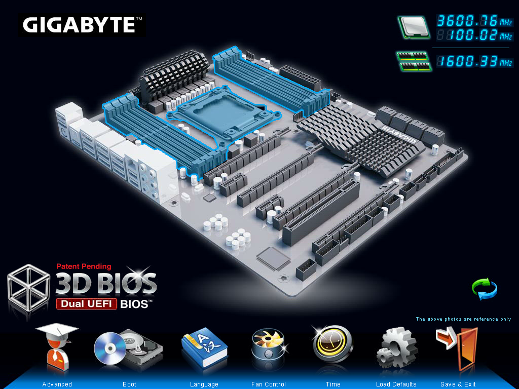
As an initial screen, I am a little disappointed, as it contains almost zero information. The image of the motherboard may or may not be the motherboard that is actually being used (we saw similar scenarios on other Gigabyte motherboards), and we get no details about what is actually installed - motherboard name/model, CPU used, memory amount, temperatures, voltages, fan speeds et al. As a system builder or debugger, this information is vital so I do not have to go rummaging inside a possibly dusty case.
This main screen separates the BIOS up into different areas that the user can click or highlight, and as I have specified in previous reviews, it would be great if these areas that change color also provide a popup that tell the user what it is they are selecting. Each of the areas (CPU + Memory, PCIe, IO Panel, SATA, Chipset) brings up a menu similar to that found in the 'Advanced' section of the BIOS. Along the bottom are options to enter the advanced mode, change language, or the fan controls:
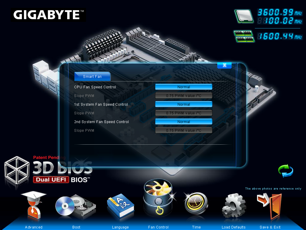
Once again we see an odd-ish system for users to control their fans - by the magical 'PWM Value / ºC' units. Clearly, we can work out that the higher the number, the quicker the fan ramps up in speed, but there are infinitely better ways to handle this. At the low level, we have ASRock who utilize 'Levels' of how quickly the fans ramp up, taking out the units altogether, but let us look at this objectively.
The BIOS has access to CPU speeds, CPU temperatures, and the PWM value of the fan. Given the fan controller used on board, we may also have access to the RPM value of that fan. It does not take a software genius to code a system that means that the user can utilize a percentage of the peak PWM value for various temperatures, and the software to control the gradients in between a multipoint user-defined system. If there is access to RPM values, then the system could initiate a test to see what PWM values correlate to what RPM, and how much this is of the max RPM (as the relationship between RPM and power applied is not always linear). Then give the user a graphical interface in order to control this, apply a multipoint gradient and possible hysteresis with spinning down the fans as well as spinning them up. I struggle to see the complexity of such a system (maybe there is more to it than meets the eye) given the controls at hand - the nearest solution we have to this is ASUS' technology, which works rather well.
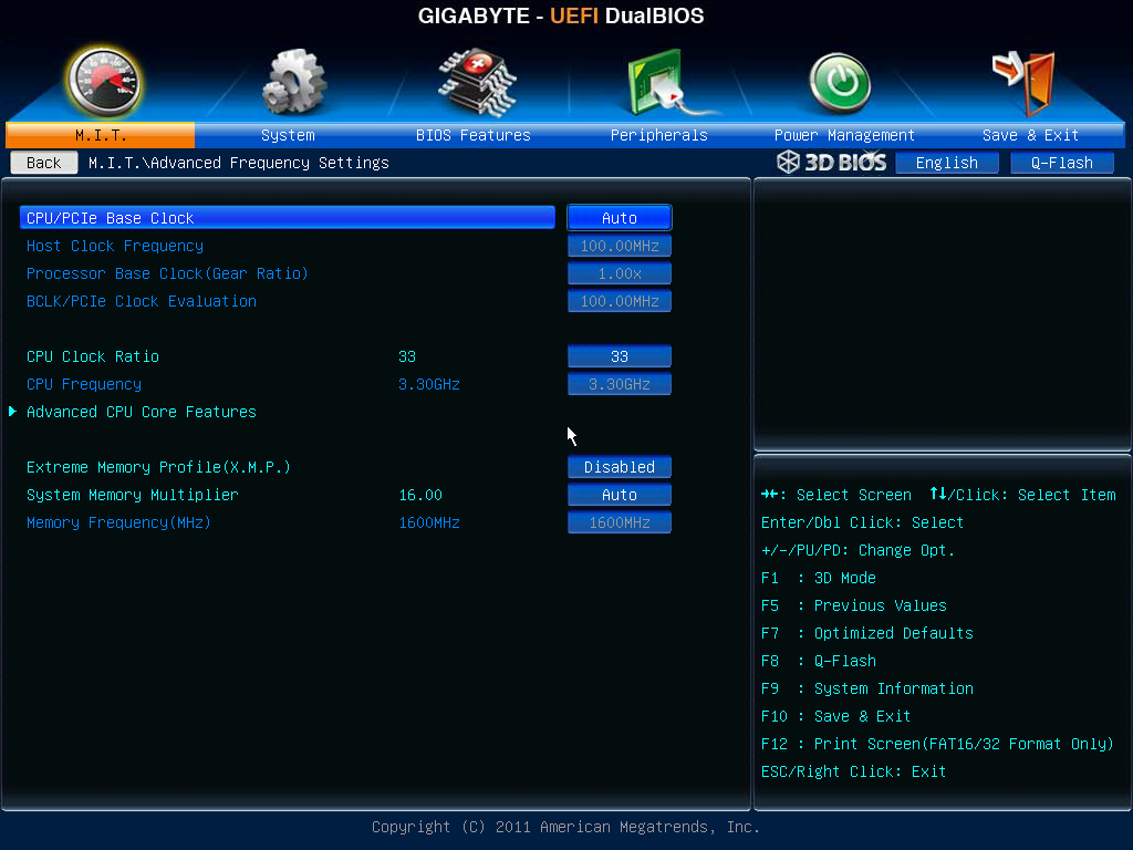
Rant on fan speeds aside, the main set of screens I am usually interested in within the BIOS start in the advanced menu:
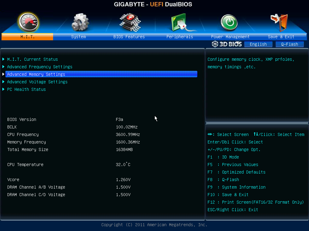
The first screen is our overclocking option menu, designated 'M.I.T.'. From here, we get more of the information out of the BIOS, such as the BIOS version, CPU speed, memory speed, CPU temperature and voltages. The five menu options provide us with a more detailed look at the settings of the board, such as frequencies, memory settings, voltages, power delivery and PC 'health' (fan speeds and temperatures).
For overclocking, the options are a little around the place, requiring multiple clicks or button presses to get to everything important. We can change the CPU speed via the frequency menu, but CPU voltages are found in a sub-menu of the voltage settings. For Load Line Calibration, this is found under a different sub-menu of the voltage settings. Memory multiplier can be adjusted in either the frequency settings or memory settings, but sub-timings are dealt with in a sub-menu of the memory settings - memory voltages are changed through a different sub-menu of the voltage settings. If that wasn't enough, turbo modes, PLL overvoltages and Cx state options are in a sub-menu of frequency settings. There are better ways of laying the information out - it feels like a BIOS designed by an engineer, rather than an enthusiast user.
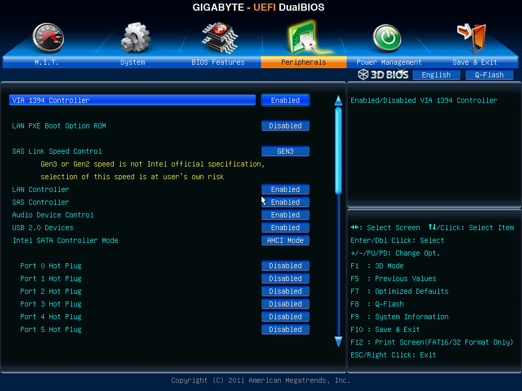
Other BIOS options of note are in the peripherals section. Because of using the C606 chipset, we have those SAS enabled ports that also support SATA drives. As mentioned in the visual inspection, these are specified to be routed to the chipset via a PCIe 1.0 link to ensure data integrity. If a user would like more speed (i.e. greater than 1.0 GBps), then the option to change the SAS Link Speed Control is now available from the F3a BIOS onwards.


Gigabyte X79S-UP5 WiFi Software
When I reviewed the ASRock X79 Extreme11, due to the upgraded audio and LSI chips, we had a lot of software to show you and discuss. However as the Gigabyte X79S-UP5 WiFi is essentially half the price, our audio is standard and the CPU routing is normal - in essence we get the same software package on the UP5 that we normally do on the rest of the Gigabyte X79 range. This means a dash of EasyTune6 and some @BIOS.
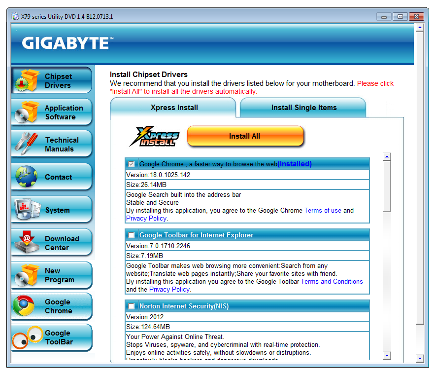
The driver install is quick and painless as it uses the silent installation options available for all the drivers required. One click of a button will install all the drivers and some of the software. For other software, such as 3TB Unlock or 3D Power, has to be installed manually.
It should be noted that Gigabyte often releases new software in the middle of a product line or after a launch. Since Sandy Bridge-E was released, we have two packages that fall into this category - Gigabyte Tweak Launcher and USB Blocker. The former is an easier overclocking tool than ET6 as it forgoes the GUI, but unfortunately at the time of reviewing it was not configured for C606 usage. The latter we will discuss here.
USB Blocker
Gigabyte has a lot of industry consumers that come to them with specific requests and tight financial budgets they have to adhere with. Because of this, we see that Gigabyte often has a mountain of SKUs listed on their website that differ very slightly (USB 3.0 ports here, no VGA output there), but in reality they may only sell a SKU in India or Malaysia rather than worldwide. One of the requests that has filtered down from industry is the requirement to protect their machines from attacks via USB by any means necessary. Asides from an anti-virus, Gigabyte has implemented their USB Blocker software. This gives the admin (USB Blocker software requires a password to be set) to select what sorts of USB devices can be attached to the system.
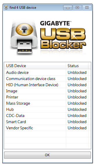
Apparently if you block all USB ports for everything, including mice and keyboards, the only way around it is a PS/2 device, or if the board does not have a PS/2 port, loading into safe mode and uninstalling the software. This also begs the question whether if the program was removed from the boot-up sequence if it would still be blocking devices. The USB Blocker should be linked in some way to the BIOS, so it can be cut off at source - but then again, if the rear IO has a reset BIOS button that could be a way around it. With this feature, I feel that manufacturers may have to start adding in USB ports physically to the board (above the 24-pin ATX power connector) like in server boards that cannot be disabled from mice/keyboards.
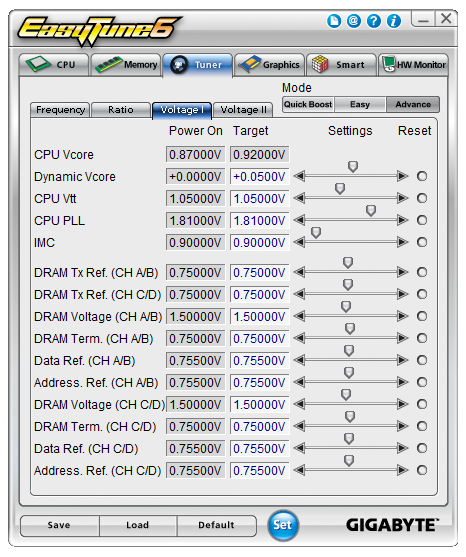
EasyTune6
The stalwart of the Gigabyte software package, for a long time now, has been EasyTune6. As a result I have to say it is looking dated. The software itself allows users to apply a series of predefined overclocks, adjust voltages, check CPU and Memory details, modify the GPU speeds (with compatible GPUs), adjust fan controls and monitor temperatures.
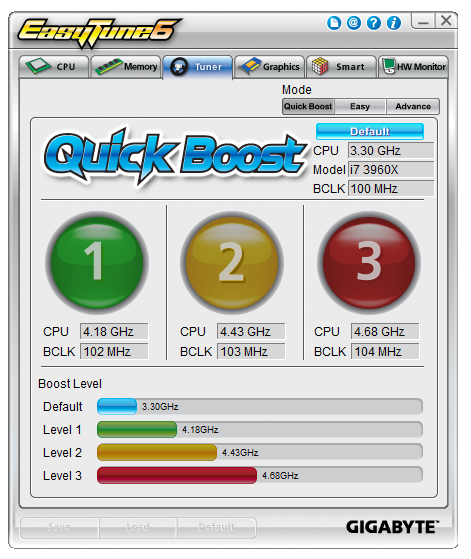
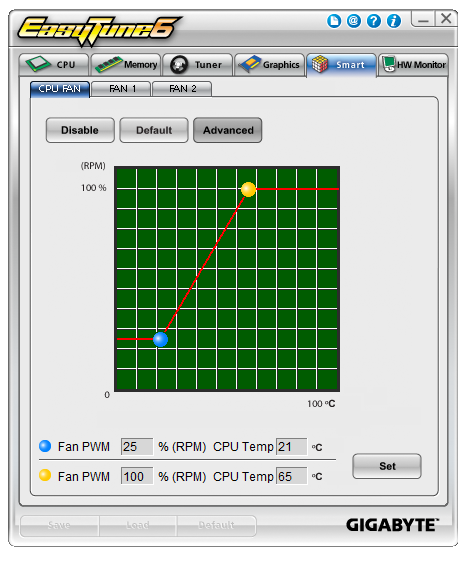
Software controls for the fans are similarly simple like the ones in the BIOS, except this time the user can use the mouse to define the gradient used for the fans in terms of CPU temperature and %RPM (note no mention of PWM values here).
There is still a minor flaw with EasyTune6, or with the BIOS. On some Gigabyte motherboards, ET6's hardware monitor interferes with the CPU in processing requests, and as a result can cause the deferred procedure call (DPC) latency to jump by factor 20. This is important for audio requests, whereby if the DPC latency is high, aural pops and cracks could possibly be heard. On some motherboards though, this problem never arises, due to either a different software version or BIOS update. Unfortunately, with the X79S-UP5 WiFi, this is an error. Given the issues we have had with NumLock on the F3a BIOS, both should be corrected in the near future.
@BIOS
Motherboard manufacturers should have two things in their motherboard arsenal relating to BIOS updating - at least one way of updating the BIOS from the BIOS, and a software alternative. Most manufacturers adhere to this (there are some exceptions). The reason for having two methods gives a selective way of updating, but also in the past I have experienced that certain major updates are not recognized by the tool in the BIOS, and as such have to update through software (which is more flexible). @BIOS is Gigabyte's software tool:
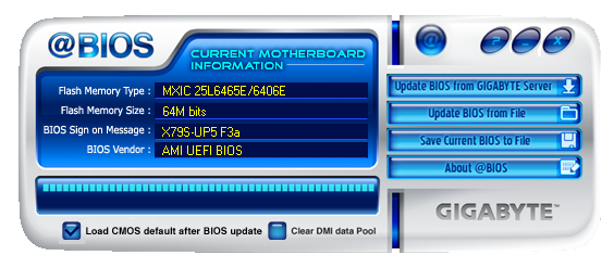
@BIOS can either update from a file, or check the Gigabyte servers for the latest version. All we need now is to wrap this software with USB Blocker and ET6 all under one software package, rather than three different installs.


Gigabyte X79S-UP5 WiFi In The Box
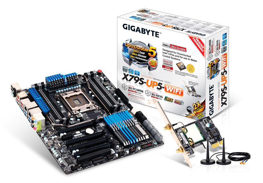
Gigabyte's high-end packages of late have been overflowing with extras in the box. When we shell out over $300 for a product, there has to be something in the box that makes it worthwhile. In the case of the X79S-UP5 WiFi, we get:
Driver CD
WiFi CD
User Manual
Rear IO Place
Six SATA Cables
USB 3.0 Front Panel
PCIe x1 WiFi card
Two Antenna
USB to 4-pin Floppy Cable
Flexible Crossfire Connector
Flexible SLI Connector
Rigid 3-way SLI Connector
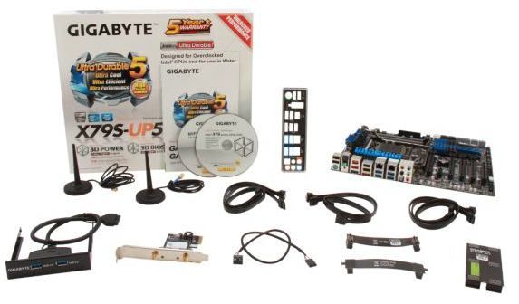
If we directly compare the box of the ASRock X79 Extreme11, a $600 product, to that of this $330 motherboard, they are essentially the same, except that the Gigabyte board comes with the WiFi card, antenna and other peripherals, but without some molex to SATA cables.
Gigabyte X79S-UP5 WiFi Overclocking
Experience with Gigabyte X79S-UP5 WiFi
For an X79 board, the Gigabyte X79S-UP5 WiFi has a few minor flaws when it came to overclocking. Namely at the time of the latest BIOS when this board was tested, neither the settings for Load Line Calibration or PLL overvoltages worked. (The first of these is to help stabilize voltage, the second is important for Sandy Bridge processors to work over 4.6 GHz.) Gigabyte is now aware of these, so they may be fixed in a later BIOS.
Despite a workstation board not having overclocking as a focus, Gigabyte employs two different features to ensure that a user can boost the CPU speed. The first is MultiCore Enhancement, which allows the processor to run at the top turbo bin no matter the loading (read this article to learn more about MCE), which becomes enabled when XMP is enabled. The next is the OC button on the back of the IO panel. When enabled (pressed down and light is on), the CPU gets a mild push in overclocks and voltages.
Automatic overclocking was a little flawed - the options available in EasyTune were not happy with various memory kits or even at their own settings. As this motherboard uses the C606 chipset, we also get no 'Auto Tuning' option, and Gigabyte Tweak Launcher does not work. For manual overclocks, the fact that the BIOS even when selected has trouble with LLC and PLL Overvoltage means there is a hard limit to overclocking. For example on the LLC front - when the BIOS is set to LLC Extreme and 1.400 volts, the CPU in the OS will register 1.356 volts at load, rather than ~1.400 volts as expected.
Methodology:
Our standard overclocking methodology is as follows. We select the automatic overclock options and test for stability with PovRay and OCCT to simulate high-end workloads. These stability tests aim to catch any immediate causes for memory or CPU errors.
For manual overclocks, based on the information gathered from previous testing, starts off at a nominal voltage and CPU multiplier, and the multiplier is increased until the stability tests are failed. The CPU voltage is increased gradually until the stability tests are passed, and the process repeated until the motherboard reduces the multiplier automatically (due to safety protocol) or the CPU temperature reaches a stupidly high level (100ºC+).
Our test bed is not in a case, which should push overclocks higher with fresher (cooler) air. We also are using Intel's All-in-one Liquid Cooler with its stock fan. This is a 120mm radiator liquid cooler, designed to mimic a medium-to-high end air cooler.
Automatic Overclock:
The options for automatic options come from the OC Button on the back IO panel of the motherboard, or the three options found in EasyTune 6. Here we go through them one by one.
When the OC button was enabled, the system would apply a different set of turbo bins to our processor. Instead of 39x/39x/38x/38x/37x/36x as expected, the system would boost single core performance to 4.2 GHz. This resulted in improved benchmark scores (131.49 in 3DPM Single Thread vs. 123.27 at stock) with no discernable increase in temperature.
Under ET6, the OC Level 1 option was selected - this gave the system a 41x multiplier and 102 MHz BCLK for a total overclock to 4182 MHz. This setting left both the BIOS voltage and CPU LLC on automatic. In the OS, we saw a load voltage of 1.296 volts, and XMP was applied automatically. This gave peak temperatures of 57ºC during PovRay and 60ºC during OCCT.
The OC Level 2 option gave the system a 43x multiplier and 103 MHz BCLK for a total overclock to 4429 MHz. This setting was stable during PovRay, giving 59ºC as a peak temperature, but produced errors during OCCT.
The OC Level 3 option should have applied a 44x multiplier and 104 MHz BCLK for a total overclock to 4576 MHz, however this setting was completely unstable and the board refused to POST.
Manual Overclock:
For our manual overclocking the BIOS is the place to go. By default, we enabled PLL Overvoltage (to enable overclocks above 4.6 GHz) and set the CPU Load Line Calibration to Extreme for CPU voltage stability. As with other testing, we started with the 44x multiplier.
At the 44x multiplier, the system was stable with a setting of 1.375 volts in the BIOS. This led to a reading of 1.332 volts at load in the OS, and peak temperatures of 62ºC during PovRay and 64ºC during OCCT.
At the 45x multiplier, the system was stable with a setting of 1.425 volts in the BIOS. This led to a reading of 1.380 volts at load in the OS, and peak temperatures of 66ºC during PovRay and 68ºC during OCCT.
At the 46x multiplier, no setting selected would boot successfully. The power limits were adjusted to 500W, the voltage in the BIOS upped to 1.500 volts, but the system refused to boot at all. This leads me to believe that the PLL Overvoltage setting in the BIOS is not properly configured, or is a limiting feature of the chipset as a whole that restricts the CPU.
Many thanks to...
We must thank the following companies for kindly donating hardware for our test bed:
OCZ for donating the Power Supply and USB testing SSD
Micron for donating our SATA testing SSD
G.Skill for donating our memory kits
ASUS for donating AMD GPUs and some IO Testing kit
ECS for donating NVIDIA GPUs
Test Setup
| Processor | Intel i7-3960X (6C/12T, 3.3 GHz) |
| Motherboards | Gigabyte X79S-UP5 WiFi |
| Cooling | Intel All-In-One Liquid Cooler |
| Power Supply | OCZ 1250W Gold ZX Series |
| Memory | GSkill RipjawsZ 4x4 GB DDR3-2400 9-11-11 Kit 1.65 V |
| Memory Settings | XMP |
| Video Cards |
ASUS 7970 3GB GDDR5 ECS GTX 580 1536MB |
| Video Drivers |
Catalyst 12.3 NVIDIA Drivers 296.10 |
| Hard Drive |
Corsair Force GT 60GB Micron RealSSD C300 256GB |
| Case | Open Test Bed - CoolerMaster Lab V1.0 |
| Operating System | Windows 7 64-bit |
| SATA Testing | Micron RealSSD C300 256GB |
| RAID Testing | ADATA SX910 256GB |
| USB 2/3 Testing | OCZ Vertex3 240GB |
Power Consumption
Power consumption was tested on the system as a whole with a wall meter connected to the OCZ 1250W power supply, while in a dual 7970 GPU configuration. This power supply is Gold rated, and as I am in the UK on a 230-240 V supply, leads to ~75% efficiency > 50W, and 90%+ efficiency at 250W, which is suitable for both idle and multi-GPU loading. This method of power reading allows us to compare the power management of the UEFI and the board to supply components with power under load, and includes typical PSU losses due to efficiency. These are the real world values that consumers may expect from a typical system (minus the monitor) using this motherboard.
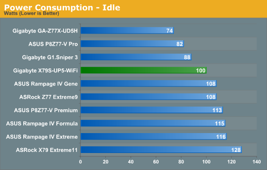
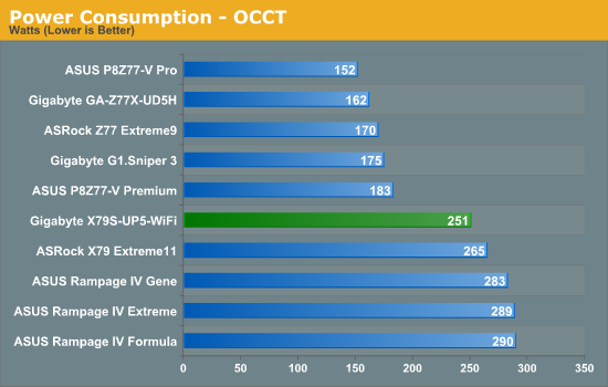
As far as our X79 testing goes regarding power, the X79S-UP5 takes top spot. This would seem to suggest that the new ICs on board actually do make a power saving.
POST Time
Different motherboards have different POST sequences before an operating system is initialized. A lot of this is dependent on the board itself, and POST boot time is determined by the controllers on board (and the sequence of how those extras are organized). As part of our testing, we are now going to look at the POST Boot Time - this is the time from pressing the ON button on the computer to when Windows starts loading. (We discount Windows loading as it is highly variable given Windows specific features.) These results are subject to human error, so please allow +/- 1 second in these results.
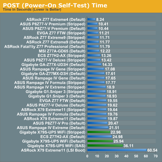
The Gigabyte X79S-UP5 WiFi takes a long time to boot in our standard booting scenario - more if the SAS ports are being used.
USB Speed
For this benchmark, we run CrystalDiskMark to determine the ideal sequential read and write speeds for the USB port using our 240 GB OCZ Vertex3 SSD with a SATA 6 Gbps to USB 3.0 converter. Then we transfer a set size of files from the SSD to the USB drive using DiskBench, which monitors the time taken to transfer. The files transferred are a 1.52 GB set of 2867 files across 330 folders – 95% of these files are small typical website files, and the rest (90% of the size) are the videos used in the Sorenson Squeeze test.
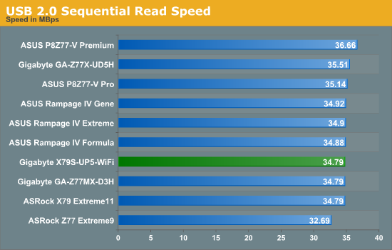
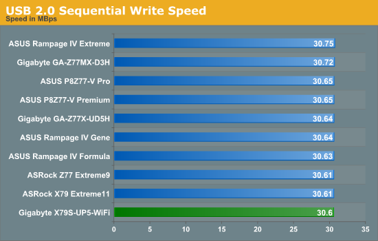
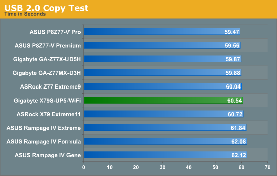
As USB 2.0 comes from the chipset, not much changes between Z77 and X79.
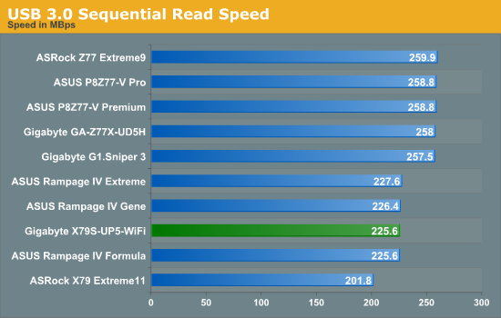
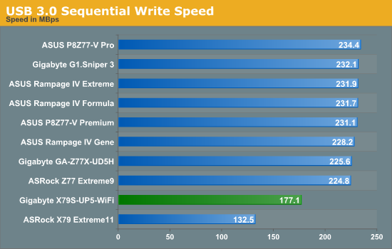
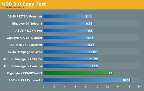
For USB 3.0, we are split between Z77 which uses the chipset, and X79 which uses controllers. On the ASUS we had ASMedia controllers, on the ASRock X79 Extreme11 it was Texas Instruments, and we have VIA USB 3.0 to deal with on the X79S-UP5. While the Via perform better than the TI, they still lag behind ASMedia.
SATA Testing
We also use CrystalDiskMark for SATA port testing on a C300 drive. The sequential test (incompressible data) is run at the 5 x 1000 MB level. This test probes the efficiency of the data delivery system between the chipset and the drive, or in the case of additional SATA ports provided by a third party controller, the efficiency between the controller, the chipset and the drive.
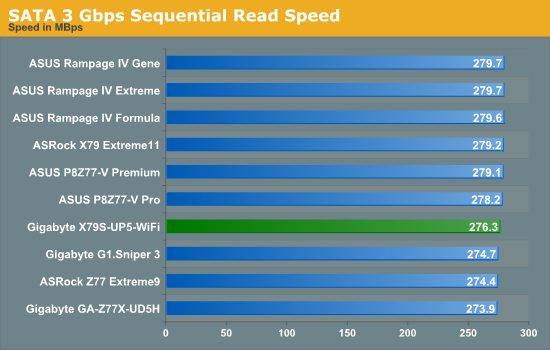
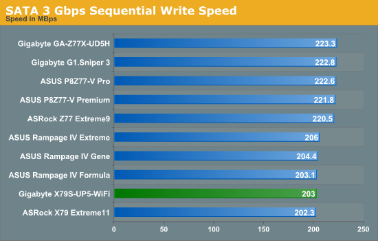
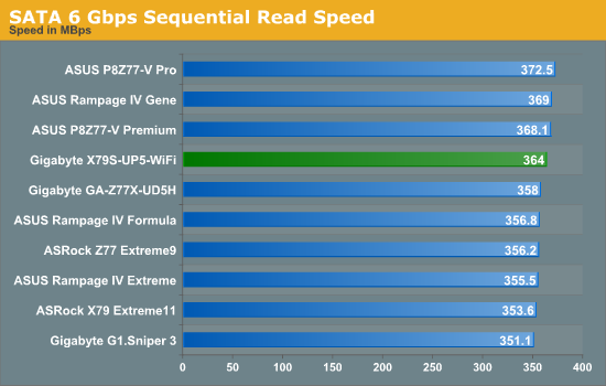
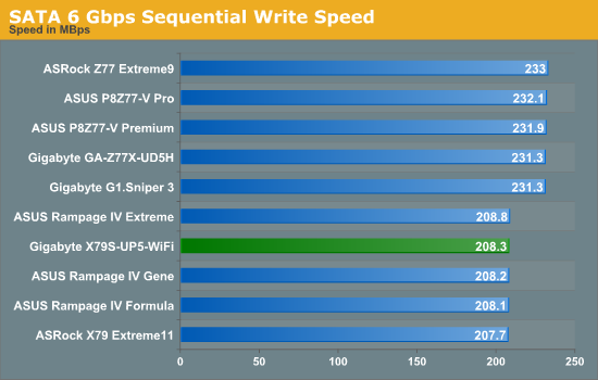
Nothing odd to report in our SATA testing - SATA write speeds on X79 lag behind Z77 as a general rule.
DPC Latency
Deferred Procedure Call latency is a way in which Windows handles interrupt servicing. In order to wait for a processor to acknowledge the request, the system will queue all interrupt requests by priority. Critical interrupts will be handled as soon as possible, whereas lesser priority requests, such as audio, will be further down the line. So if the audio device requires data, it will have to wait until the request is processed before the buffer is filled. If the device drivers of higher priority components in a system are poorly implemented, this can cause delays in request scheduling and process time, resulting in an empty audio buffer – this leads to characteristic audible pauses, pops and clicks. Having a bigger buffer and correctly implemented system drivers obviously helps in this regard. The DPC latency checker measures how much time is processing DPCs from driver invocation – the lower the value will result in better audio transfer at smaller buffer sizes. Results are measured in microseconds and taken as the peak latency while cycling through a series of short HD videos - under 500 microseconds usually gets the green light, but the lower the better.
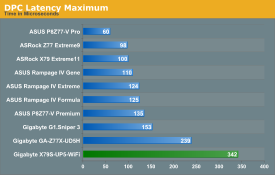
The DPC result for the X79S-UP5 was a little odd. Initially it was to do with EasyTune 6 interfering with the result, giving a value often 20x that shown here. However when it was turned off, the DPC seemed to have other issues:
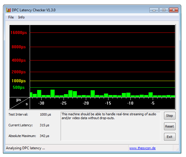
This DPC behavior is quite odd, suggesting that something onboard is polling the CPU by default.
3D Movement Algorithm Test
The algorithms in 3DPM employ both uniform random number generation or normal distribution random number generation, and vary in various amounts of trigonometric operations, conditional statements, generation and rejection, fused operations, etc. The benchmark runs through six algorithms for a specified number of particles and steps, and calculates the speed of each algorithm, then sums them all for a final score. This is an example of a real world situation that a computational scientist may find themselves in, rather than a pure synthetic benchmark. The benchmark is also parallel between particles simulated, and we test the single thread performance as well as the multi-threaded performance.
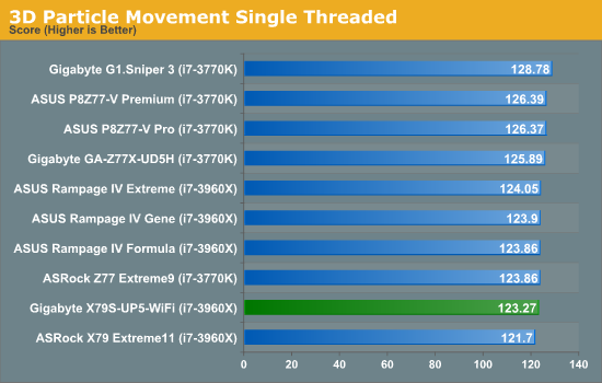
With our socket 2011 refresh boards, it seems single thread performance is a little low. This is a little strange.
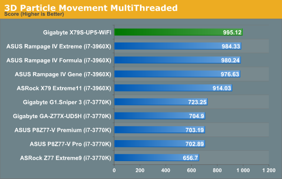
In terms of multithreaded results, the X79S-UP5 takes advantage of MultiCore enhancement with a Sandy Bridge-E processor, and manages to beat our previous top runners in the ROG boards.
WinRAR x64 3.93 - link
With 64-bit WinRAR, we compress the set of files used in the USB speed tests. WinRAR x64 3.93 attempts to use multithreading when possible, and provides as a good test for when a system has variable threaded load. If a system has multiple speeds to invoke at different loading, the switching between those speeds will determine how well the system will do.
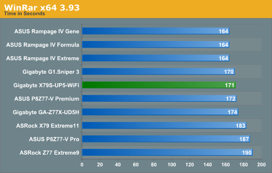
ASUS' adaptive algorithm for WinRAR cannot be beat it seems, however the X79S-UP5 still puts up a fight. It lags behind the G1.Sniper 3 using the 4C/8T i7-3770K, suggesting that the WinRAR test loves MHz and IPC more than cores.
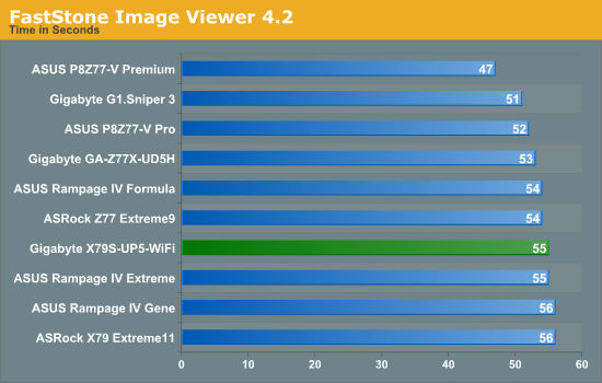
FastStone Image Viewer 4.2 - link
FastStone Image Viewer is a free piece of software I have been using for quite a few years now. It allows quick viewing of flat images, as well as resizing, changing color depth, adding simple text or simple filters. It also has a bulk image conversion tool, which we use here. The software currently operates only in single-thread mode, which should change in later versions of the software. For this test, we convert a series of 170 files, of various resolutions, dimensions and types (of a total size of 163MB), all to the .gif format of 640x480 dimensions.
Xilisoft Video Converter
With XVC, users can convert any type of normal video to any compatible format for smartphones, tablets and other devices. By default, it uses all available threads on the system, and in the presence of appropriate graphics cards, can utilize CUDA for NVIDIA GPUs as well as AMD APP for AMD GPUs. For this test, we use a set of 32 HD videos, each lasting 30 seconds, and convert them from 1080p to an iPod H.264 video format using just the CPU. The time taken to convert these videos gives us our result.
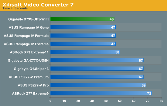
The Gigabyte does well on our XVC test, taking top spot similar to the 3DPM-MT test.
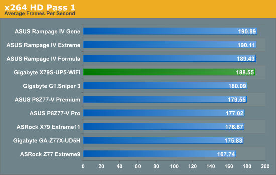
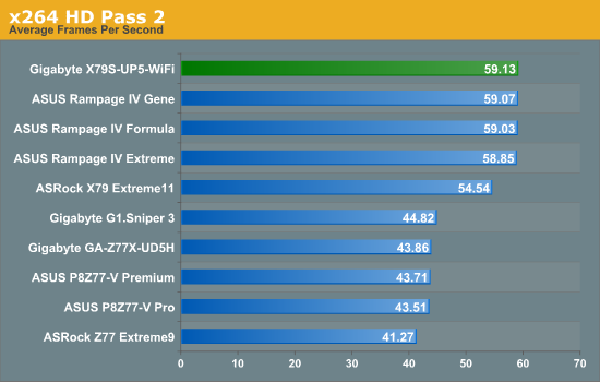
x264 HD Benchmark
The x264 HD Benchmark uses a common HD encoding tool to process an HD MPEG2 source at 1280x720 at 3963 Kbps. This test represents a standardized result which can be compared across other reviews, and is dependant on both CPU power and memory speed. The benchmark performs a 2-pass encode, and the results shown are the average of each pass performed four times.
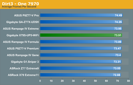
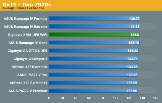
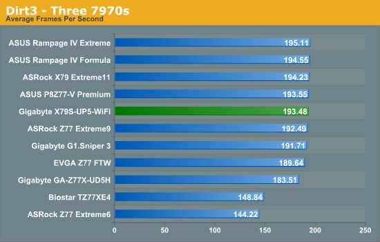
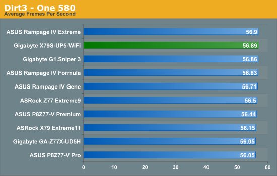
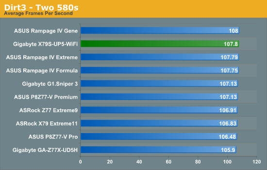
Dirt 3
Dirt 3 is a rallying video game and the third in the Dirt series of the Colin McRae Rally series, developed and published by Codemasters. Using the in game benchmark, Dirt 3 is run at 2560x1440 with full graphical settings. Results are reported as the average frame rate across four runs.
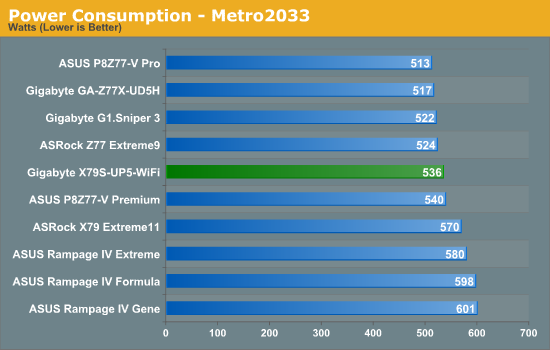
Metro2033
Metro2033 is a DX11 benchmark that challenges every system that tries to run it at any high-end settings. Developed by 4A Games and released in March 2010, we use the inbuilt DirectX 11 Frontline benchmark to test the hardware at 2560x1440 with full graphical settings. Results are given as the average frame rate from 4 runs.
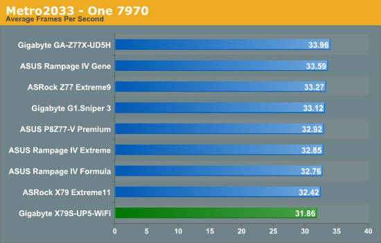
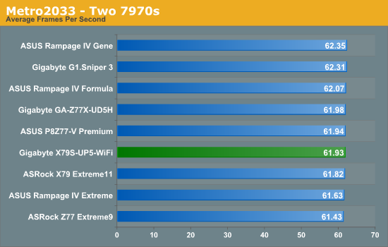
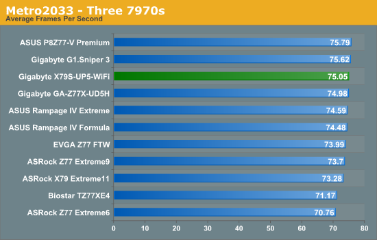
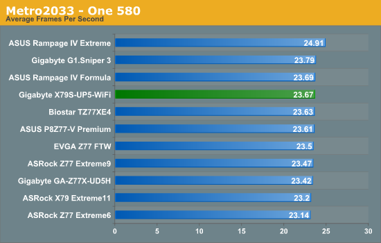
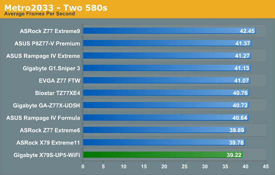
With a native set of x16/x16/x8 lanes onboard, the X79S-UP5 seems to do fine with gaming testing, matching our other X79 boards.
With the X79 and Sandy Bridge-E platform coming to the middle of its run, we were expecting at least some of the motherboard manufacturers to update their high end lines in order to inject new enthusiasm to the platform that potentially has the bigger profit margins. So far we have had a pair of products that meet this quota - the ASRock X79 Extreme11 which aims itself to be a full bodied workstation product by implementing dual PLX chips and an LSI SAS PCIe 3.0 chip, but comes in at $600. The other is essentially its direct competitor - the $330 Gigabyte X79S-UP5 WiFi that we have reviewed today.
For the money, Gigabyte is also marketing the X79S-UP5 WiFi as a workstation board. It uses the C606 server chipset rather than the X79 consumer chipset - this gives the system access to enterprise storage solutions (SAS ports) more chipset bandwidth to deal with increased IO, and access to Xeon processors with ECC support natively. We get 14 ports for SATA devices, eight of which are also capable of dealing with SAS drives. We tested the SAS ports with high-powered SATA drives and got a peak throughput of 2.38 GBps with a tweak of the BIOS settings.
Gigabyte is also using the X79S-UP5 WiFi to highlight their new Ultra Durable 5 methodology. For the user this means an improved version of their power delivery by using International Rectifier PowIRstage IR3550 ICs, reported of being capable of up to 60A current and up to 60ºC cooler than traditional power delivery. In reality, this means less phases needed on the board (cheaper) but also up to 20ºC cooler than Ultra Durable 4, resulting in higher overclocks if the power delivery was the limiting factor. Though from what we have heard, these IR3550s do not come cheap, so for the time being they are on high-end boards only, rather than ITX boards where they could be very useful.
Elsewhere onboard we have dual NIC (one Intel, one Realtek), a Realtek ALC898 audio codec, a setup to allow three full length PCIe dual slot GPUs (or two and a pair of PCIe cards like the bundled WiFi card), 12 USB 2.0 ports, 6 USB 3.0 ports (from Via and Fresco controllers), five fan headers, TPM and some legacy in the IEEE 1394 and PS/2 connections.
In terms of performance, the X79S-UP5 WiFi benefits from the recent swathe of MultiCore Enhancement enabled boards from the Z77 chipset. As that seems to becoming the standard, it was enabled on the X79S-UP5 WiFi and as a result it keeps pace with the ROG boards (which also have MCE) ahead of the other X79 products. With a little push of the OC button at the back, we also go all the way up to 11 with 4.2 GHz at our disposal on an i7-3960X.
If I were to criticize the board, it would be on a few points to make. Firstly, as an enthusiast / hobbyist builder / family solver of all things PC, I like a two-digit debug on board to help diagnose faults. In addition, I am not too keen on a separate WiFi card - I would like space in order to maximize the airflow between the GPU slots, thus if WiFi was included we should aim for a mini-PCIe card or IO back panel solution like ECS. Given the pricing between the non-WiFi and WiFi versions of the UD3H/UD5H, the card adds $30 to the box - without it at $300 could be a preferred SKU for many customers. The BIOS needs some tweaking to enable the higher overclocks, NumLock, and sorting out the DPC issue.
Back when I published my ROG article, I listed the then current prices of the popular X79 boards of the time. Here is the same list, with the ASRock X79 Extreme11 and Gigabyte X79S-UP5 added (note we have reviewed over half of these, awards are listed).
$600 - ASRock X79 Extreme11 - Bronze Award for innovation
$445 - EVGA X79 Classified
$430 - ASUS Rampage IV Extreme - Silver Award for innovation and performance
$390 - MSI Big Bang-XPower II - Bronze Award for features
$370 - ASRock X79 Champion
$370 - ASUS Rampage IV Formula
$350 - Gigabyte G1. Assassin2
$345 - ASRock X79 Extreme9
$330 - Gigabyte X79S-UP5
$320 - ASUS P9X79 Pro - Silver Award for innovation and performance during early X79
$310 - ECS X79R-AX Black Extreme - Bronze Award while on rebate
$290 - EVGA X79 SLI
$280 - ASUS Rampage IV Gene - Bronze Award for innovation for mATX
$265 - Intel DX79SI
$260 - ASUS P9X79
$260 - ASRock X79 Extreme7
$240 - Gigabyte X79-UD3
$235 - ASRock X79 Extreme4
$230 - Biostar TPower X79
$225 - ASRock X79 Extreme4-M
The Gigabyte X79S-UP5 fits right in the middle, and perhaps a non-WiFi SKU would look more favorable at the $300 price point. The X79S-UP5 does not necessarily innovate from the chipset point of the view - we are simply swapping in a C606 chipset on what is normally an X79 board, thus opening up some SAS functionality. We could argue that the ECS X79R-AX is a cheaper board to have SAS functionality, but it is guaranteed on the Gigabyte board, as opposed to 'Your Mileage May Vary' on the ECS. What we do get however is use of the Ultra Durable 5 PowIRstage IR3550 ICs, which should help reduce power consumption. However, this 'innovation' still costs a pretty penny to the consumer end.
Workstation boards thrive on stability, functionality, and that extra bit of performance can help immensely with the extreme and heavy-duty workloads. As a workstation product, this board would be a good recommendation. Though given the BIOS and DPC issues, if audio is your thing then it might be worth waiting for a few more BIOS updates to ensure an element of rigidity in that context. Gamers and normal users can still use this board to - it is set out well for a dual GPU setup, and with all the SATA ports there will never be any problems with storage. Hit the OC button on the back and a mild CPU overclock should help any game you throw at it. However if you are comfortable with the BIOS for some mild OC, do not need server features, or want better fan controls mixed with a good software package, then there are a few other boards that offer a cheaper alternative.


