Original Link: https://www.anandtech.com/show/1033
Intel's E7205: Granite Bay Hits the Streets
by Evan Lieb on November 18, 2002 9:56 AM EST- Posted in
- Motherboards
Intel has undoubtedly regained all that they have lost in the chipset market. There was a period in time when Intel was only able to claim sales by forcing motherboard manufacturers to produce motherboards based on their chipsets but today, most motherboard manufacturers are more than excited about virtually all of Intel's chipset lines.
One interesting chipset that has been on the radar for months is Granite Bay; the first dual channel DDR solution for the Pentium 4, Granite Bay was supposed to be an entry-level Pentium 4 workstation solution. However, its feature set combined with a very pro-DDR market made Granite Bay the perfect successor to Intel's RDRAM based 850E solution as the top performer in the Pentium 4 market.
Today, Intel has finally unveiled Granite Bay and dubbed the chipset E7205 to go along with their server/workstation class chipset nomenclature. Despite the target market for the chipset, the three motherboards we have rounded up today based on the new 7205 chipset can be used as either entry level workstations or high-end desktop motherboards. In fact, a good number of E7205 partners will have enthusiast boards as well as entry level workstation solutions available.
Before we get to the boards themselves it's important to look at a few of the key features of the E7205 chipset:
- Dual Channel DDR266 Memory Bus (4.2GB/s memory bandwidth)
- 400/533MHz FSB Support (3.2GB/s - 4.2GB/s FSB bandwidth)
- AGP 8X support
- USB 2.0 support
What's interesting to note here is that the chipset only supports dual channel DDR266 and is not validated for dual channel DDR333 operation. It won't be until Intel moves to a 667MHz FSB before we see dual channel DDR333 support for single processor Pentium 4 systems simply because of bandwidth requirements.
With that out of the way, let's start looking at the first E7205 based motherboards.
ASUS P4G8X Deluxe: Basic Features
|
Motherboard Specifications |
|
|
CPU
Interface
|
Socket-478
|
|
Chipset
|
Intel
E7205 MCH
Intel 82801DB ICH4 |
|
Bus
Speeds
|
100
- 400MHz (in 1MHz increments)
|
|
Core
Voltages Supported
|
up
to 1.975V (in 0.025V increments)
|
|
I/O
Voltages Supported
|
N/A
|
|
DRAM
Voltages Supported
|
up to 2.7V
in 0.1V increments
|
|
Memory Slots
|
4 184-pin
DDR DIMM Slots
|
|
Expansion Slots
|
1 AGP
8X Slot
5 PCI Slots |
|
Onboard RAID
|
N/A
|
|
Onboard USB 2.0/IEEE-1394
|
USB
2.0 supported through South Bridge
TI TSB43AB22 FireWire Controller |
|
Onboard LAN
|
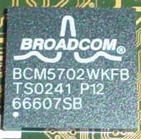
Broadcom
5702 Gigabit LAN
|
|
Onboard Audio
|
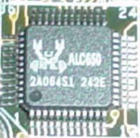
Realtek
ALC650
|
|
Onboard Serial ATA
|
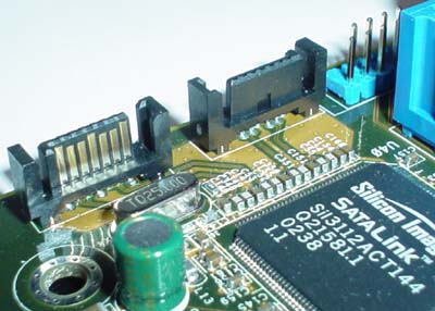
Silicon
Image 3112A controller
|
|
BIOS
Revision
|
1001
|
Taking a quick peak at all the features the P4G8X offers, we can clearly see that ASUS is staying with their series of cutting-edge features motherboards, now called the Deluxe series of ASUS motherboards. As an all-in-one solution (minus VGA), ASUS's Deluxe series looks to be a real winner now and into the foreseeable future. Only ABIT's MAX series is as competitive.
One of the first features we happened to notice was the LAN chip ASUS decided to use with their P4G8X. This isn't your usual LAN chip; in actuality, it's a Gigabit LAN chip, which supports up to 1000Mbit/s bandwidth. The Gigabyte LAN is powered by Broadcom's 5702 chip, one we're quite familiar with at this point. Setting up this particular Gigabit LAN was no more difficult than any of the other thousands of 10/100 solutions we've configured. Unfortunately, there aren't a lot of mainstream users (that includes your Joe Average as well as your power user) that will be able to take advantage of Gigabit support. This technology is usually regulated to small businesses or any institution for that matter that requires a large network.
ASUS doesn't choose a very intriguing sound chip despite the high-end nature of this motherboard. A simple and very mainstream Realtek ALC650 codec is chosen to power the onboard sound of the P4S8X. This sound solution offers nothing special or interesting compared to other solutions we've used before.
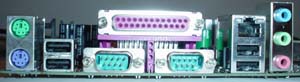
The P4G8X's I/O configuration isn't all that unusual either. We see some pretty common features like two PS/2 ports, two serial ports, one parallel port, four rear USB 2.0 ports, a Gigabit LAN port, and Mic In, Line In, and Line Out, which drive the onboard sound. No dual LAN here, but Gigabit should be adequate for most.
ASUS uses a Serial ATA chip we've seen on several motherboards before, including Intel's D845PEBT2, Epox's 4PEA+, and ECS's L4S8A. This SATA chip turns up on ASUS's P4G8X Deluxe board, dubbed the Silicon Image 3112A. This chip is capable of supporting up to two independent Serial ATA devices as well as RAID 0 (striping) and RAID 1 (mirroring). While certainly a nice feature, all current onboard Serial ATA implementations use the PCI bus, which translates into limited bandwidth. We would rather see native Serial ATA support in a chipset, because this way a Serial ATA device won't have to fight for bandwidth with other PCI devices, whereas the current implementation on modern-day motherboards are forced to travel through the PCI bus.
As far as IDE support goes, the ASUS P4G8X doesn't come with an abundance of options. The Primary and Secondary IDE connectors support two channels each, or four IDE devices in total. This is good only if you're the type that doesn't need more than a DVD drive, CD-RW drive, two hard drives, or some other combination thereof. Therefore, if you need to connect more than four drives or desire onboard IDE RAID, the P4G8X isn't for you.
The E7205 chipset provides support for USB 2.0 like its 845PE predecessor. The Intel ICH4 South Bridge makes this support possible; up to six USB 2.0 ports total. The P4G8X doesn't include any additional USB 2.0 support (for example, through a separate onboard USB 2.0 chip), but the P4G8X already has four rear USB 2.0 ports in addition to a two-port USB bracket that you can plug into the onboard USB header and which is bundled with the Deluxe Edition, so not too many people should be disappointed.
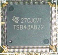
Another technology we like to see included is FireWire support. While there aren't any rear FireWire ports, there are two (red) FireWire headers at the bottom of the P4G8X. The headers are powered by TI's TSB43AB22 FireWire controller, which supports no more than two FireWire ports. If you're interested in how this FireWire controller works, head on over to TI's features page on the TSB43AB22, they list all the features about this controller that you could want to know.
ASUS P4G8X Deluxe: Board Layout
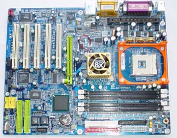
There weren't too many layout issues to report with this particular E7205-based motherboard. We had only a few minor complaints.
Looking at the positioning of the ATX (20-pin) connector, we see that ASUS placed it on the right-hand side of the motherboard. This is the best place to position an ATX connector, as the thick wires won't obstruct the installation/uninstallation of the HSF or passive North Bridge heatsink, as well as any other components that you may decide to modify or uninstall. Unfortunately, the ATX connector isn't located high enough; the ideal position would be at the very top, right-hand corner of the motherboard, perhaps directly over the silk-screened CPU multiplier options.
All three onboard fan headers are placed well. The chassis and power fan headers are placed at the very edge of the right-hand portion of the motherboard. This way, fan wires won't have to travel far to their destination. The third fan header however (the CPU fan header) was placed a bit too close to the CPU clamps and DIMM connectors. This makes it somewhat difficult to sneak your fingers in this area to unplug the CPU fan line, but it shouldn't be too much of an issue unless you have large fingers.
As is now common with almost all P4 motherboards, the ATX12V connector is located on the left-hand side of the motherboard. This isn't the best location for the ATX12V connector though (especially since it's located towards the midsection of the motherboard), as this connector ends up in your path of uninstalling the HSF. The ATX12V connector should be placed at the very top of the motherboard, somewhere on the right-hand portion of the board preferably.
We're glad that ASUS places the Primary/Secondary IDE connectors to the right of the DIMM slots and just above the midsection of the motherboard. We've experienced what a hassle it can be to have the Primary/Secondary IDE connectors placed on the lower portion of the motherboard. It makes it more difficult for the IDE cables to reach to the uppermost bays of a large-sized ATX case, and might have even get tangled up with our video card.
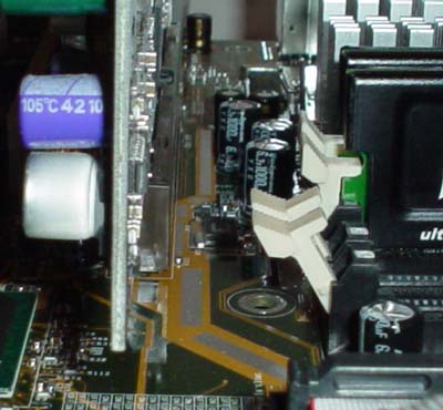
There are a lot of motherboard makers that place their DIMM connectors too close to where the video card is installed. However, ASUS doesn't make this mistake, and places their DIMM connectors far enough away from our GeForce4 Ti4600 and with a little room to spare, as is apparent in the picture below. We always like it when mainboard manufacturers do this because we're not forced to uninstall the video card if we want to uninstall memory.
Some of the other onboard features that ASUS includes on the P4G8X Deluxe (but that have nothing to do with performance) is ASUS's patented EZ Plug technology. EZ Plug is made possible by a standard 4-pin AUX connector, which all modern-day ATX power supplies carry. EZ Plug functions as a replacement for the ATX12V connector that the vast majority of P4 motherboards contain, and that ASUS includes anyway. While not incredibly useful, it's a nice feature to have nonetheless.
The USB and FireWire headers are positioned fairly well. There is a single USB header on this motherboard, located at the bottom of the board below the blue PCI slot (more on this PCI slot shortly). This is the best place to position the USB header, as it has little chance of getting tangled up with any other wires or hardware components. The two red FireWire headers are located nicely as well, nearly at the bottom of the motherboard. They might be a bit too high, especially if you were to make use of the onboard Serial ATA connectors, as the FireWire and Serial ATA cables would cross over each other, resulting in potential clutter. This isn't too much of an issue however.
Finally, we have the blue PCI slot. Here's how ASUS describes this technology, dubbed "Blue Magic":
Besides supporting all the conventional PCI applications, the Blue Magic Slot also supports wireless LAN cards. The great thing about the feature is that it supports 802.11a, 802.11b and Bluetooth standards, making the A7V8X the first motherboard with all three standards. ASUS is planning to introduce a wireless LAN card later this year equipped to handle the three standards.
ASUS P4G8X Deluxe: BIOS and Overclocking
The P4G8X utilizes Phoenix Technology's Award BIOS, which seems to be the most popular BIOS for power users these days.
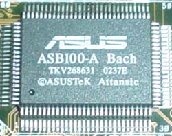
BIOS hardware monitoring is powered by ASUS's ASB100-A Bach chip. The Hardware Monitor section includes some fairly normal readings and information in general.
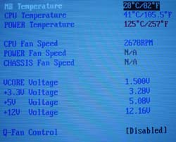
Here you'll find readings on motherboard temperature, CPU temperature, power temperature, fan speeds (CPU, power, and chassis), Vcore, PSU readings (all rails), and an option for enabling ASUS's Q-fan technology. Q-fan is a nice little BIOS option to have, as it regulates your CPU's fan speed based on how taxed your system is at any given moment. CPU temp readings were right where we expected them to be, between 39C and 41C.
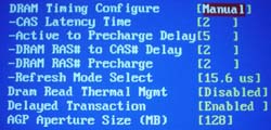
Normally called the Advanced Chipset Features section, the Chip Configuration section included some fairly nice DRAM tweaking as well as other such options.
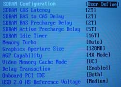
In Chip Configuration, it's possible to adjust DRAM timing mode, CAS Latency, Precharge to Active, Active to Precharge, Active to CMD, and Idle Timer (which doesn't really boost performance at all) among other minor options. There are no Bank Interleave or Command Rate adjustments available, but that's normal for Intel-chipset based motherboards these days. All in all, the Chip Configuration section lives up to the tweaker's needs for the most part.
With Intel's E7205 chipset, the highest memory speed possible is 266MHz (dual channel operated) if your FSB is operating at stock speed (133MHz). Since there are no other divider options available in the BIOS or via onboard jumpers or switches, the only way you can increase your memory speed is by increasing your FSB. If you raise the FSB of your processor to 166MHz (666MHz effective FSB), assuming you have a good enough processor, you can run your memory at DDR333 (dual channel). However, since dual DDR266 already maxes out the bandwidth that 533MHz FSB Pentium 4 processors can handle, there's no need to overclock unless, of course, you're an overclocker.
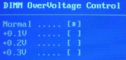
The P4G8X BIOS does include some fairly good voltage tweaking options. In 0.1V increments, you can adjust VDIMM up to 2.7V, which is adequate for most users, considering that overvolting memory doesn't usually yield a significantly better overclock. VAGP is also adjustable in 0.1V increments; as high as 1.7V.
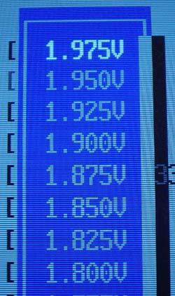
ASUS goes all out with the Vcore options, allowing as high as 1.975V in 0.025V increments. 1.975V should be plenty for most people, as running any modern day Pentium 4 CPU at 1.975V will significantly reduce the lifespan of the CPU. For once, ASUS produces a board that doesn't overvolt, since Vcore (as read through the Hardware Monitor) consistently reads a dead-on 1.5V.
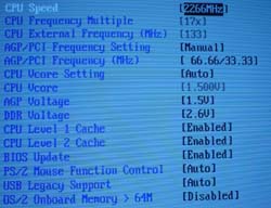
Like every other 845-based motherboard we've tested in the past, the ASUS P4G8X comes with an independent AGP/PCI lock running at 66.67MHz/33.33MHz, and adjustable all the way up to 104.46MHz/52.63MHz. This is a vital feature to have for overclockers, as running your AGP or PCI cards too far out of spec can damage those parts. For non-overclockers, it's still a nice BIOS option to have.
Overclocking the ASUS P4G8X Deluxe was a cinch. The following table lists the components we used for overclocking the FSB:
|
Front Side Bus Overclocking Testbed |
|
|
Processor:
|
Pentium
4 2.26GHz
|
|
CPU
Vcore:
|
1.5V
(actual)
|
|
Cooling:
|
Intel
Retail HSF & Thermal Pad
|
|
Power
Supply:
|
Enermax
300W
|
This is quite a conservative and cheap overclocking setup, but every since its inception P4 Northwood processors have continually been able to outperform AMD's Thoroughbred processors overclocking-wise, making us more impressed by the day with Intel's 0.13-micron process. That said, we were easily able to hit 160MHz FSB, or just over 2.70GHz core clock. This is certainly not out of the ordinary for an Intel chipset based motherboard.
We weren't able to conduct any memory overclocking tests due to the fact that this motherboard only contains a 1:1 divider. However, have no fear, ASUS is coming out with a motherboard based on SiS' 655 chipset, which supports dual channel DDR333. It'll be interesting to see how much performance gain there is with dual channel memory running at 400MHz and beyond on SiS 655 motherboards.
ASUS P4G8X Deluxe: Stress Testing
The P4G8X had some pretty decent stress testing potential, mostly because it's based on a dual channel chipset (E7205), which is a more complex and difficult chipset to implement (due to signal integrity, among other issues) than the conventional single channel DDR chipsets that dominate today's markets. Still, we managed to test this board in several different areas and configurations, including:
- Chipset and motherboard stress testing was conducted by running the FSB at 160MHz.
- Memory stress testing was conducted by running RAM at 266MHz and 320MHz in dual DDR operation (two modules each) at the most aggressive timings possible.
Front Side Bus Stress Test Results:
Our FSB stress tests at 160MHz proved to be completely successful. Prime95 torture tests were run in the background for a grand total of 30 hours straight, during which time we performed some general tasks like data compression, various DX8 games (JKII, etc.), and light apps like Word and Excel. We also decided to further stress the P4G8X by randomly rerunning SPECviewperf 7.0, Sciencemark, and XMPEG, all of which couldn't faze the P4G8X.
Memory Stress Test Results:
Our first memory stress test tests how well the P4G8X is able to handle the stock, rated speed the Intel E7205 chipset is validated for (namely dual DDR266 operation). Here were the timings we were able to achieve at the following settings:
|
Stable DDR266 Timings |
|
|
Clock
Speed:
|
133MHz
|
|
Timing
Mode:
|
Turbo
|
|
CAS
Latency:
|
2
|
|
Bank
Interleave:
|
N/A
|
|
Precharge to Active:
|
2T
|
|
Active
to Precharge:
|
5T
|
|
Active
to CMD:
|
2T
|
|
Command Rate:
|
N/A
|
These are exactly the timings you want to see in a truly good dual channel motherboard. You won't be able to squeeze any more performance from your memory with these timings, as there aren't any other BIOS options that would increase performance.
Since the P4G8X doesn't have any other memory dividers other than 1:1, we decided to test how aggressive we could set DRAM timings to running at dual DDR320 (160MHz FSB). Here were our results:
|
Stable DDR320 Timings |
|
|
Clock
Speed:
|
160MHz
|
|
Timing
Mode:
|
Turbo
|
|
CAS
Latency:
|
2
|
|
Bank
Interleave:
|
N/A
|
|
Precharge to Active:
|
2T
|
|
Active
to Precharge:
|
5T
|
|
Active
to CMD:
|
2T
|
|
Command Rate:
|
N/A
|
We see that the P4G8X is able to handle the same aggressive timings at DDR320 as it did at DDR266. Very impressive, but we have to admit, it isn't anything we haven't seen before from dual DDR nForce boards. Still, it's nothing to complain about.
Our final memory test deals with one of the more stressful situations we can think of with the P4G8X. Lets see what happens with all four memory slots full running at 266MHz:
|
Stable DDR266 Timings |
|
|
Clock
Speed:
|
133MHz
|
|
Timing
Mode:
|
Turbo
|
|
CAS
Latency:
|
2
|
|
Bank
Interleave:
|
N/A
|
|
Precharge to Active:
|
2T
|
|
Active
to Precharge:
|
5T
|
|
Active
to CMD:
|
2T
|
|
Command Rate:
|
N/A
|
This is exactly what we like to see. With all four memory banks populated, CAS 2-2-2-5 in Turbo mode is very possible. We used four identical Corsair XMS modules (rated at CAS2 DDR400) for this test. However, mixing memory modules with all four DIMMs populated isn't impossible by any means. With two Corsair XMS modules and two Mushkin modules installed, we were able to just as reliably operate the P4G8X as we were with identical Corsair modules.
As usual, we ran several memory stress tests and general apps to make sure all these timings were stable. We started off by running Prime95 torture tests; a grand total of 24 hours of Prime95 was successfully run at the timings listed in the above charts. We also ran Sciencemark (memory tests only) and Super Pi. Neither stress test was able to bring the P4G8X to its knees.
ASUS P4G8X: Tech Support and RMA
For your reference, we will repost our tech support evaluation procedure here:
The way our Tech Support evaluation works is first we anonymously email the manufacturer's tech support address(es), obviously not using our AnandTech mail server to avoid any sort of preferential treatment. Our emails (we can and will send more than one just to make sure we're not getting the staff on an "off" day) all contain fixable problems that we've had with our motherboard. We then give the manufacturer up to 72 hours to respond over business days and will report not only whether they even responded within the time allotted but also if they were successful in fixing our problems. If we do eventually receive a response after the review is published, we will go back and amend the review with the total time it took for the manufacturer to respond to our requests.
The idea here is to encourage manufacturers to improve their technical support as well as provide new criteria to base your motherboard purchasing decisions upon; with motherboards looking more and more alike every day, we have to help separate the boys from the men in as many ways as possible. As usual, we're interested in your feedback on this and other parts of our reviews so please do email us with your comments.
ASUS's RMA policy is pretty straight forward as follows:
Dear Sir/Madam
Please provide the following information so that we may process your request for warranty repair service. Once we have obtained that information from you, we will issue an RMA # and provide the proper shipping instructions. Please read and provide all of the information below. We cannot complete your request, if all of the information below is not provided.
Thank you,
ASUS Computer International
PLEASE PROVIDE US WITH:
1) THE MODEL & SERIAL NUMBER OFF OF YOUR PRODUCT
model (name of product) serial# (10 digits/characters long, no dashes)
2) YOUR FULL NAME/NAME OF COMPANY (Only provide company name if the shipping address is to a company).
3) YOUR SHIPPING ADDRESS (no PO boxes please)
4) YOUR DAYTIME PHONE/FAX NUMBER
ASUS Computer International (USA) is a warranty repair service center. Please contact place of purchase for credit, refund, upgrade, or advance replacement. Asus does not provide these services under any circumstances.ASUS Does not cover physical damage. Please refer to page 2 of your users manual. There is a $15.00 fee to replace a broken socket. There is a $40.00 fee to repair all other physical damage. If a product is not repairable, the product will be sent back to the customer. If a product is sent in with physical damage and is not accompanied with a payment, the product will be rejected and customers will not be reimbursed for shipping charges. A payment can be made by check, money order (payable to ASUS), or a credit card#. The payment must be sent in with the damaged product. Customers from Canada must make payments with a credit card#.
This is a fairly cut and dry RMA policy, with nothing too special that stands out. As is the norm with motherboard makers, you're asked for quite a bit of information in regards to exactly what has to be RMAed. Everything else is self-explanatory.
Before, we were critical of ASUS for not providing more information about their RMA policy on their web site. We still are critical of ASUS in this regard, as it is still difficult to this day to find any RMA information on their web site except that you can email someone at [email protected]. We recently sent off an anonymous email to ASUS (at [email protected]) asking them if we could RMA an ASUS motherboard to them in addition to inquiring as to exactly what their RMA policy entails. It's interesting to know that ASUS answered our RMA questions in only 15 hours. This, of course, is very impressive. However, we're still baffled that ASUS hasn't made their RMA information easily accessible on their web site yet.
ASUS's tech support response time was much better than the last time we checked. It took ASUS over 200 hours (weekends not included in those hours) to respond to our tech support inquires the last time around. This time, it took "only" 71 hours for tech support to respond to our email, an hour shy of our standard 72 hour limit. ASUS's remedy for our mock problems was spot-on, so we're certainly pleased about that. But otherwise, ASUS needs to improve their tech support response time.
ASUS's RMA policy is straight forward and not too difficult to complete, but their tech support is still lacking in a big way.
Gigabyte 8INXP Rev.1: Basic Features
|
Motherboard Specifications |
|
|
CPU
Interface
|
Socket-478
|
|
Chipset
|
Intel
E7205 MCH
Intel 82801DB ICH4 |
|
Bus
Speeds
|
100
- 200MHz (in 1MHz increments)
|
|
Core
Voltages Supported
|
up
to 1.725V (in 0.025V increments)
|
|
I/O
Voltages Supported
|
N/A
|
|
DRAM
Voltages Supported
|
up
to 2.8V in 0.1V increments
|
|
Memory Slots
|
4 184-pin
DDR DIMM Slots
|
|
Expansion Slots
|
1 AGP
8X Slot
5 PCI Slots |
|
Onboard RAID
|
Promise
PDC20276
|
|
Onboard USB 2.0/IEEE-1394
|
USB
2.0 supported through South Bridge
No FireWire |
|
Onboard LAN
|
Intel
RC82540EM Gigabit LAN
|
|
Onboard Audio
|
Realtek
ALC650
|
|
Onboard Serial ATA
|
Silicon
Image 3112A controller
|
|
BIOS
Revision
|
D10b
|
With the introduction of Intel's E7205 chipset, Gigabyte has initiated a new marketing campaign centered around the word "dual". Gigabyte is marketing the 8INXP as "The 6-Dual Miracle". The six features that make the 8INXP the "6-dual miracle" are:
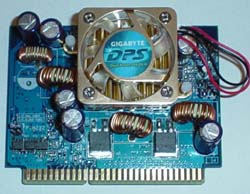
- Dual Power System (DPS): this is a separate, add-in card that gives the 8INXP 6-phase power circuitry instead of 3-phase. Gigabyte claims that, in Parallel mode (versus Backup mode), DPS is able to deliver better system stability (especially while overclocked) in addition to longer onboard components life. Skip to the BIOS and Overclocking section for our test results with DPS installed.
- Dual Logical Processors: this is nothing more than Gigabyte's way of saying their board supports Intel's Hyper Threading technology.
- Dual Channel DDR: this is pretty self-explanatory. As you should know by now, Gigabyte's 8INXP motherboard uses Intel's E7205 (Granite Bay) chipset, which supports Dual DDR266 operation, for a peak memory bandwidth of 4.27GB/s.
- Dual RAID: this is Gigabyte's way of saying their board supports both Serial ATA RAID and IDE RAID. Read on to find out more about these two features.
- Dual BIOS: this feature is also fairly self-explanatory. The 8INXP supports two BIOS chips. This feature is nice to have if you corrupt your first BIOS chip (e.g. you lose power to your system as you're updating your primary BIOS). You can switch over to the second BIOS chip in this situation, and hot have to go through the trouble of correcting the issue through other, time-consuming means.
- Dual Cooling: this is the least interesting of the six "dual miracles". The North Bridge HSF and DPS HSF form the "Dual Cooling" feature. Yes, this is very cheesy.
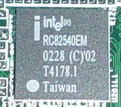
For LAN, Gigabyte goes with Gigabit technology. Gigabyte chooses Intel's RC82540EM Gigabit chip for onboard LAN; this chip supports up to 1000Mbit/s bandwidth and is found in only one other recent P4 motherboard that we know of (MSI's 845PE Max2-FIR). Setting up Gigabit via the onboard Intel controller was a cinch, and not any more difficult than setting up the P4G8X's Broadcom Gigabit LAN in addition to any other 10/100 solution.
Moving on, we see that Gigabyte decided to choose Realtek's ALC650 chip for onboard sound. This 6-channel solution isn't anything special really, and is found on the vast majority of motherboards these days. It's interesting to note that we haven't encountered a motherboard without onboard sound in the last few months. This says a lot about the fierce competition in the motherboard market.
The 8INXP's I/O configuration is pretty normal for the most part. Some of the I/O ports include features like two PS/2 ports, two serial ports, one parallel port, a Game port, two rear USB 2.0 ports, a Gigabit LAN port, and Mic In, Line In, and Line Out, which drive the onboard sound.
Gigabyte decides to slap on the latest and "greatest" feature for an onboard device by including Silicon Image's 3112A Serial ATA controller. We just discussed this SATA chip in the ASUS P4G8X section, but there are a few other motherboards that use this SATA controller as well, including the Intel D845PEBT2, Epox 4PEA+, and ECS L4S8A. The 3112A is capable of supporting up to two independent Serial ATA devices, as well as RAID 0 (striping) and RAID 1 (mirroring). As we've said before, we'd rather wait for chipset makers to integrate SATA into their South Bridges before we get excited about how Serial ATA drives and devices will perform.
The 8INXP's IDE support is much better than the P4G8X's. As is standard now, the Primary and Secondary IDE connectors support two channels each, or up to four IDE devices total. In addition, there are two other IDE connectors, powered by the onboard Promise PDC20276 RAID controller. Each of the two IDE RAID connectors supports 2 channels each, and therefore up to four IDE devices. In total, you can hookup a grand total of 8 IDE devices, in addition to two SATA devices via the two onboard SATA connectors. Most users should be happy with this amount of device support. Before we forget, we should mention that the PDC20276 RAID controller itself supports RAID 0 (striping) and RAID 1 (mirroring) arrays. For more information on Promise's PDC20276 controller, head on over to their product information page here.
USB 2.0 support is powered by Intel's South Bridge, aka ICH4. This means the Gigabyte 8INXP is capable of supporting up to six USB 2.0 ports. In addition to the two rear USB 2.0 ports, there are also two USB headers at the bottom of the board. Gigabyte throws in a four-port USB bracket that connects to both USB headers. This is very nice to have as you don't have to take the trouble to go out and purchase a USB bracket
Unfortunately, this board did not come with FireWire. This feature would have really made the 8INXP a complete solution, but it's a minor setback nonetheless.
Gigabyte 8INXP: Board Layout
We had some minor complaints about the layout of this board, but not too many overall.
Looking at the positioning of the ATX (20-pin) connector, we see that Gigabyte places it on the right-hand side of the motherboard. This is the best place to position an ATX connector, as the thick wires won't obstruct the installation/uninstallation of the HSF or passive North Bridge heatsink, as well as any other components that you may decide to modify or uninstall. The ATX connector should be located a bit higher, ideally at the very top, right-hand corner of the motherboard.
All three onboard fan headers are placed well. The system and power fan headers are located at the edge of the right-hand portion of the 8INXP. This way, fan wires won't have to travel far to their destination. The third fan header however (the CPU fan header) was placed a bit too close to the CPU clamps and DIMM connectors. This makes it somewhat difficult to sneak your fingers in there to unplug the CPU fan line, but this isn't too much of an issue unless you have large fingers.
As is now common with almost all P4 motherboards, the ATX12V connector is located on the left-hand side of the motherboard. This isn't the best location for the ATX12V connector though (especially since it's located towards the midsection of the motherboard), as this connector ends up in your path of uninstalling the HSF. The ATX12V connector should be placed at the very top of the motherboard, somewhere on the right-hand portion of the board preferably.
We're glad that Gigabyte places the Primary/Secondary IDE connectors to the right of the DIMM slots and just above the midsection of the motherboard. We've experienced what a hassle it can be to have the Primary/Secondary IDE connectors placed on the lower portion of the motherboard. It makes it more difficult for the IDE cables to reach to the uppermost bays of a large-sized ATX case, and might have even got tangled up with our video card.
There are a lot of motherboard makers that place their DIMM connectors too close to where the video card is installed. However, Gigabyte is good enough not to make the same annoying mistake, and places their DIMM connectors far enough away from our GeForce4 Ti4600. We always like it when mainboard manufacturers do this because we're not forced to uninstall the video card if we want to uninstall memory.
There are two, well-positioned USB headers on this motherboard, located at the bottom of the board below the two green IDE RAID connectors. This is the best place to position the USB headers, as it has little chance of getting tangled up with any other wires or hardware components.
Gigabyte 8INXP: BIOS and Overclocking
Not surprisingly, we see that Gigabyte uses the Award BIOS.
The PC Health section includes a good deal of information, although pretty average by today's standards.
In PC Health you'll find only one temperature reading, CPU temperature. This reading ended up fluctuating between 45-47C, which is unusual because we're used to seeing CPU temperatures between 38 and 43C with our particular 2.26B Pentium 4 CPU. Perhaps this is simply an early BIOS issue. Other PC Health readings include fan speeds for the CPU, power, and system fan headers. Vcore and PSU readings (all rails) are also included, and are normal for the most part. Finally, we see that there are four "Warnings" options in PC Health. These include CPU warning temperature, CPU fan failure warning, power fan failure warning, and system fan failure warning. Fan failure warnings are a nice little feature to have, since fan failure is not that uncommon.
Gigabyte continues their recent trend of hiding the Advanced Chipset Features section in the 8INXP BIOS. You have to press and hold CTRL while hitting the F1 key to bring up the Advanced Chipset Features section in the BIOS. Some readers have emailed us asking why Gigabyte hides this feature in their BIOS, and even we were stumped for a while before we got an answer. Gigabyte's explanation is quite simple; they don't want users messing with DRAM timings, as it can cause system instability. We think this is fair, especially since Gigabyte does mention the CTRL + F1 feature in their manual.
As far as the features in the Advanced Chipset Features section are concerned, there isn't anything we haven't seen before. You're allowed to adjust CAS Latency, Precharge to Active, Active to Precharge, Active to CMD, and a handful of other options that don't boost performance whatsoever. We weren't astonished to see the absence of Bank Interleave or Command Rate options, since we can't remember the last time we encountered a BIOS for an Intel chipset based motherboard that had these options. You'll see Command Rate and Bank Interleave options in SiS 648 motherboards more often than not. All in all, DRAM tweaking is fair, and the Top Performance feature (located outside of Advanced Chipset Features) is a nice plus.
As should be expected with all Granite Bay motherboards from this point on, Gigabyte's 8INXP contained absolutely no divider adjustments besides 1:1. There were no onboard jumpers or switches that could have changed this fact either. This isn't surprising, as all you really need is a 533MHz FSB processor and two modules that can ran at 266MHz or better to squeeze out the best performance from your system. This assumes you don't overclock since, as we mentioned before, the only way you can increase your memory speed beyond 266MHz with a Granite Bay motherboard is by increasing the FSB.
Voltage adjustments are fairly plentiful in the 8INXP BIOS. VDIMM is adjustable as high as 2.8V in 0.1V increments, which should be adequate for all users, including most memory overclockers. VAGP is also quite adjustable; in 0.1V increments you can adjust VAGP all the way up to 1.8V. Video card overclockers will have no gripes with this type of voltage flexibility.
Vcore options are pretty good for this particular motherboard. Since most P4 overclockers don't really need to raise Vcore to get a large overclock, having the ability to raise Vcore anywhere past 1.6V or so really isn't necessary (using a 1.5V Northwood CPU of course). This BIOS allows for "only" 1.725V in 0.025V increments. Vcore reads steady at 1.5V according to PC Health, so hitting an actual 1.725V should be a reality. So, while not spectacular, the Vcore ceiling for this BIOS is acceptable.

Additionally, we see that the 8INXP BIOS includes the much welcomed AGP/PCI lock feature. We've become accustomed to seeing this feature on almost all 845-based as well as nForce-based motherboards in the last year or so, and we welcome the day SiS and VIA motherboards start fully implementing AGP/PCI lock functions. This AGP/PCI lock is also adjustable as high as 48MHz/97MHz instead of the stock 66MHz/33MHz if you are interested in even more overclocking adventures. Be forewarned though, it generally isn't advisable to go higher than 70MHz/37MHz, as your AGP and/or PCI devices may fail.

We ran some overclocking tests on the Gigabyte 8INXP, which ended up performing very well in our benchmarks, as you will see shortly. The following table lists the components we used for overclocking the FSB using the 8INXP motherboard:
|
Front Side Bus Overclocking Testbed |
|
|
Processor:
|
Pentium
4 2.26GHz
|
|
CPU
Vcore:
|
1.5V
(actual)
|
|
Cooling:
|
Intel
Retail HSF & Thermal Pad
|
|
Power
Supply:
|
Enermax
300W
|
With this setup we were easily able to hit 163MHz FSB, or about 2.78GHz core clock. Looking at both the Gigabyte 8INXP and ASUS P4G8X, it becomes clear that Granite Bay boards will probably end up overclocking no worse than 845PE motherboards. However, as you'll see shortly, overclocking benchmarks are another story altogether.
We were skeptical about Gigabyte's DPS (Dual Power System) system at first, even if it did turn the 8INXP into a 6-phase motherboard. After numerous benchmarks and overclocking tests, we can safely conclude that DPS does absolutely nothing for overclocking stability or otherwise. Not surprisingly, performance was the same as was general stability. However, we would be interested in knowing if DPS does anything for the longevity of the onboard components as well as the motherboard itself.
As with the ASUS P4G8X, the Gigabyte 8INXP does not have any other dividers besides 1:1. Therefore, we weren't able to run any memory overclocking tests that would have been as worthwhile as they turned out to be in our October 7th 845PE shootout . We early await SiS 655 motherboards for this reason.
Gigabyte 8INXP: Stress Testing
The 8INXP had some pretty decent stress testing potential, mostly because it's based on a dual channel chipset (E7205), which is a more complex and difficult chipset to implement (due to signal integrity, among other issues) than the conventional single channel DDR chipsets that dominate today's markets. Still, we managed to test this board in several different areas and configurations, including:
- Chipset and motherboard stress testing was conducted by running the FSB at 163MHz.
- Memory stress testing was conducted by running RAM at 266MHz and 326MHz in dual DDR operation (two modules each) at the most aggressive timings possible.
Front Side Bus Stress Test Results:
While we were certainly happy that the 8INXP ended up being the best overclocker out of all the Granite Bay boards, we had to make absolutely sure that overclock wasn't a fluke (though our stress tests are hardly an indication of long term stability/reliability, which is near impossible to accurately measure without massive resources). We still ran our usual array of stress tests, including Prime95 torture tests, which were run in the background for a total of 24 hours. With Prime95 running in the background, we ran lots of other tasks such as data compression, various DX8 games, and light apps like Word and Excel. We reran our entire benchmark suite this time around, which includes Sysmark 2002, Quake3 Arena, Jedi Knight II, Unreal Tournament 2003, SPECviewperf 7.0, Sciencemark, and XMPEG.
All in all, the 8INXP was able to pass all of our stress tests at 163MHz FSB (Dual DDR326) with flying colors.
Memory Stress Test Results:
This first memory stress test deals with how well the Gigabyte 8INXP can handle dual DDR266. Here were the timings we were able to achieve:
|
Stable Dual DDR266 Timings |
|
|
Clock
Speed:
|
133MHz
|
|
Timing
Mode:
|
N/A
|
|
CAS
Latency:
|
2
|
|
Bank
Interleave:
|
N/A
|
|
Precharge to Active:
|
2T
|
|
Active
to Precharge:
|
5T
|
|
Active
to CMD:
|
2T
|
|
Command Rate:
|
N/A
|
These are, obviously, very good timings. What isn't shown in this graph however is that we were allowed to enable "Top Performance" in the BIOS. This speeds up the 8INXP considerably, by about 5% or so in most of our benchmarks. However, you should know that you must first load the optimized defaults in the BIOS, as this yields the most reliable and fastest results.
E7205 motherboards don't have any other memory dividers other than 1:1, so there's no way we can run memory higher than 266MHz without overclocking the FSB. Well, in this next scenario, that's exactly what we decided to do. Here were our DRAM timing results at 163MHz FSB (326MHz memory):
|
Stable Dual DDR326 Timings |
|
|
Clock
Speed:
|
163MHz
|
|
Timing
Mode:
|
N/A
|
|
CAS
Latency:
|
2
|
|
Bank
Interleave:
|
N/A
|
|
Precharge to Active:
|
2T
|
|
Active
to Precharge:
|
5T
|
|
Active
to CMD:
|
2T
|
|
Command Rate:
|
N/A
|
These are excellent timings for a chipset that isn't validated for as high as dual DDR326. Just as before, these timings were achieved with Top Performance enabled in the BIOS.
Our next memory stress tests included running 4 DIMMs at 266MHz. Here were the timings we were able to achieve:
|
Stable Dual DDR266 Timings |
|
|
Clock
Speed:
|
133MHz
|
|
Timing
Mode:
|
N/A
|
|
CAS
Latency:
|
2
|
|
Bank
Interleave:
|
N/A
|
|
Precharge to Active:
|
2T
|
|
Active
to Precharge:
|
5T
|
|
Active
to CMD:
|
2T
|
|
Command Rate:
|
N/A
|
These are excellent DRAM timings considering how many modules are installed. Due to time constraints, we were unable to test how far memory could overclock with all four DIMM slots populated. If it's any consolation, we'll be sure to include this test in our future E7205 reviews.
As usual, we ran several memory stress tests and general apps to make sure these timings were stable. We started off by running Prime95 torture tests; a grand total of 24 hours of Prime95 was successfully run at the timings and speeds listed in the above charts. We also ran Sciencemark (memory tests only) and Super Pi tests successfully. These are the exact same tests we ran on the ASUS P4G8X. All in all, we're quite happy with the outcomes.
Gigabyte 8INXP: Tech Support and RMA
For your reference, we will repost our tech support evaluation procedure here:
The way our Tech Support evaluation works is first we anonymously email the manufacturer's tech support address(es), obviously not using our AnandTech mail server to avoid any sort of preferential treatment. Our emails (we can and will send more than one just to make sure we're not getting the staff on an "off" day) all contain fixable problems that we've had with our motherboard. We then give the manufacturer up to 72 hours to respond over business days and will report not only whether they even responded within the time allotted but also if they were successful in fixing our problems. If we do eventually receive a response after the review is published, we will go back and amend the review with the total time it took for the manufacturer to respond to our requests.
The idea here is to encourage manufacturers to improve their technical support as well as provide new criteria to base your motherboard purchasing decisions upon; with motherboards looking more and more alike every day, we have to help separate the boys from the men in as many ways as possible. As usual, we're interested in your feedback on this and other parts of our reviews so please do email us with your comments.
Gigabyte's RMA policy is easy to follow and fairly good for a tier one motherboard maker like Gigabyte:
Giga-Byte offers a 1-3 year(depending on Model) manufacturer's Limited warranty. If you are experiencing difficulties in warranty service through your dealer or place of purchase, Giga-Byte may attempt to resolve this issue.
Please reply with:
Name:
Address:
Phone:
FAX:
Model number and Revision:
Serial number(10 digit): SN
Problem:
Dealer(include contact info):
CPU type + size:
Memory type + size:
This actually isn't the greatest RMA policy. Like ASUS, Gigabyte would like you to deal with the vendor you purchased your motherboard from rather than directly with them. This is understandable, as the cost of RMAs, facilities, employees, etc. can be prohibitive. Still, we would love it if the tier one guys would adopt similar RMA policies akin to Epox, Albatron, or AOpen's.
Gigabyte's tech support seems to be a bit better this time around. We received a fairly quick reply from Gigabyte within the 72 hour timeframe. To be exact, 59 hours flat. This is quite good, but again, we've seen better from smaller motherboard manufacturers. Of course, it's understandable that smaller motherboard manufacturers generally have better RMA policies and quicker tech support response time as they have to stand out somehow (in addition, smaller mainboard companies usually don't have to deal with as many problems as the larger motherboard makers do, which is another plus for needy customers).
All in all, Gigabyte's RMA policy and tech support are adequate for the most part. Compared to ASUS, Gigabyte offers about the same level of service in our experience, but it would take considerably more trial and error to better judge exactly what each motherboard maker has to offer.
Tyan S2662: Basic Features
|
Motherboard Specifications |
|
|
CPU
Interface
|
Socket-478
|
|
Chipset
|
Intel
E7205 MCH
Intel 82801DB ICH4 |
|
Bus
Speeds
|
N/A
|
|
Core
Voltages Supported
|
N/A
|
|
I/O
Voltages Supported
|
N/A
|
|
DRAM
Voltages Supported
|
N/A
|
|
Memory Slots
|
4 184-pin
DDR DIMM Slots
|
|
Expansion Slots
|
1 AGP
8X Slot
5 PCI Slots |
|
Onboard RAID
|
N/A
|
|
Onboard USB 2.0/IEEE-1394
|
USB
2.0 supported through South Bridge
No FireWire |
|
Onboard LAN
|
Intel
RC82540EM Gigabit LAN
|
|
Onboard Audio
|
Analog
Devices AD1981A SoundMAX
|
|
Onboard Serial ATA
|
N/A
|
|
BIOS
Revision
|
0.26.662
|
As is apparent from the motherboard specs listed in the above table, the Tyan S2662 is a very plain, no-nonsense motherboard for the most part.
Tyan chooses the same Gigabit chip that Gigabyte uses for their E7205 motherboard, namely RC82540EM Gigabit LAN chip. This chip supports up to1000Mbit/s bandwidth. We had no trouble setting up a LAN with this particular chip, as was the case with MSI and Gigabyte's implementation.
For onboard sound, the Tyan S2662 chooses Analog Devices' AD1981A SoundMAX chip. There really isn't anything terribly interesting to say about this sound device, expect that it is obviously AC '97 2.2 compliant. For more information on the AD1981A SoundMAX chip, head on over to this link http://products.analog.com/products/info.asp?product=AD1981A.
The S2662's I/O configuration is pretty bland, similar to Gigabyte and ASUS's I/O configurations. The S2662 features two PS/2 ports, two serial ports, one parallel port, two rear USB 2.0 ports, a Gigabit LAN port, and Mic In, Line In, and Line Out, which drive the onboard AD1981A SoundMAX chip.
The S2662's only IDE support comes in the form of two IDE connectors, the Primary and Secondary IDE connectors. Both these connectors support two channels each, for a total of four IDE devices max. There is no RAID (Serial ATA or IDE RAID) included on this motherboard, and therefore there are no other connectors for you to expand your possibilities beyond four IDE devices. If you feel that, for example, a couple optical drives and hard drives adequately fit your needs, you have nothing to worry about in terms of the S2662's IDE support. But if you want RAID or more device support you should look elsewhere.
As usual, USB 2.0 support is powered by Intel's ICH4 South Bridge. So, in total, you're able to use no more than six USB ports at a time on the S2662. We did not see any USB bracket(s) included with our motherboard, but we're not 100% certain if Tyan will be including USB 2.0 compliant brackets with their shipping S2662 motherboards, so our accessory package may not be complete. For your reference, we received a manual, driver CD, and two IDE cables plus a Floppy cable with our Tyan S2662 motherboard. Unfortunately, this board did not come with onboard FireWire as well.
Tyan S2662: Board Layout
There weren't too many issues with the S2662's layout.
In the Tyan S2662's case, the ATX (20-pin) connector is nicely placed on the right-hand side of the motherboard. This is the best place to position the ATX connector, expect that we would have liked it just a bit higher by an inch or so. This makes the installation/uninstallation of the HSF as well as any other components much easier, since the bulky ATX wires aren't obstructing your path.
There are a total of four fan headers on this motherboard, all of them positioned well. There are two fan headers each located on opposite ends of the motherboard that are positioned well enough sp that you won't have to worry about maneuvering wires inside your case. The other two fan headers are located at the top. One them, the CPU fan header is located so that we are able to unhook the CPU fan line without having to tug on the wires themselves. The other fan header is located on the opposite side of the CPU clamps, right where it should be. This way, if your case supports it, you can have a fan at the top of the case pushing air out and not have to worry about positioning the fan wires anywhere special.
The ATX12V connector is predictably placed on the left-hand side of the motherboard near the I/O ports. This location isn't ideal at all, and not just because it's on the wrong side of the motherboard but also because it's so low down on the motherboard. By placing the ATX12V connector in this particular position, you are unable to move the ATX12V line away from blocking the uninstallation of the HSF due to the fact that the ATX12V is placed so low on the motherboard and also because the ATX12V is relatively short (otherwise, if it weren't so short, we wouldn't be complaining about how low the ATX12V is being placed on the board). Still, this isn't just regulated to Tyan, as most motherboard manufacturers position the ATX12V this way.
You should have no worries about the placement of the Primary and Secondary IDE connectors, since they are close to the DIMM slots, which are located above the AGP slot. By positioning the Primary and Secondary IDE connectors (and Floppy connector) this way, we avoid the difficulty of having to extend IDE cables to reach the uppermost bays of a large ATX case. We also completely avoid cable entanglement with the video card by having these connectors placed above the AGP slot area.
The distance between the DIMM connectors and AGP slot is far enough apart from each other so that we don't have to uninstall the video card if we wanted to install/uninstall memory. This is a very welcome feature, as it is always a plus if a DIYer can cut down on some of the more mindless "busy work" activities of building a computer (like connecting a keyboard, mouse or monitor for example).
There are two USB 2.0 headers located towards the bottom of the motherboard, but not all the way down at the edge and towards the PCI slots as we would have liked. With this positioning, it's difficult to tell if Tyan has made troublesome to maneuver USB bracket wires. For your reference, Tyan doesn't include any USB brackets with their S2662 motherboard.
Tyan S2662: BIOS and Overclocking
Before we go any further, we would like to mention that Tyan isn't aiming this motherboard at tweakers, overclockers, or any other similar types of enthusiasts. They are aiming this board at users that don't want to overclock and simply need the fastest and most stable solution on the market. That's one of the reasons you don't see a huge amount of features in the BIOS or on the S2662 motherboard itself.
That said, the S2662 hardware monitor isn't all that bad. Tyan includes a couple of temperature readings in the form of CPU and motherboard temps. We also see the usual array of PSU readings (all rails). What's most interesting about this hardware monitor is that not only is there are reading for CPU fan speed, but also RPM readings for the other three onboard fan headers. This is a unique feature among motherboards, although that's about as exciting as it gets for this BIOS from our point of view.

As we've previously mentioned, this is not a tweaker's or overclocker's motherboard. Therefore, it isn't surprising to see a lack DRAM tweaking options in the form of an Advanced Chipset Features section or something similar. Of course, this goes for voltage and FSB adjustments as well, which are nonexistent.
The Tyan S2662 is no different from the other Granite Bay motherboards when it comes to divider options. At 133MHz, memory is clocked at 266MHz in the S2662 BIOS.
Tyan S2662: Stress Testing
The S2662 had some pretty decent stress testing potential, mostly because it's based on a dual channel chipset (E7205), which is a more complex and difficult chipset to implement (due to signal integrity, among other issues) than the conventional single channel DDR chipsets that dominate today's markets. However, since this BIOS allowed no overclocking whatsoever, our stress tests only consist of memory testing. Here's what we managed to include:
- Memory stress testing was conducted by running RAM at 266MHz with two banks full and at 266MHz with four banks full at the most aggressive timings possible.
Memory Stress Test Results:
Running two modules of Corsair XMS memory at dual DDR266 should be very easy for the Tyan S2662. Indeed, it was quite easy, although we were of course unable to adjust any timings since the S2662 BIOS contained no such adjustments:
|
Stable Dual DDR266 Timings |
|
|
Clock
Speed:
|
133MHz
|
|
Timing
Mode:
|
N/A
|
|
CAS
Latency:
|
N/A
|
|
Bank
Interleave:
|
N/A
|
|
Precharge to Active:
|
N/A
|
|
Active
to Precharge:
|
N/A
|
|
Active
to CMD:
|
N/A
|
|
Command Rate:
|
N/A
|
Pretty good timings, eh? No, there obviously aren't any timings we can analyze here, but if you skip a few pages to our stock benchmark testing, you'll see that the Tyan S2662 is able to compete admirably with ASUS and Gigabyte's E7205 solutions, which have been tweaked to the max for performance. At dual DDR266, the S2662 was quite stable, as it was able to complete our entire benchmark suite, which includes Sysmark 2002, Quake3 Arena, Jedi Knight II, Unreal Tournament 2003, SPECviewperf 7.0, Sciencemark, and XMPEG. Prime95 ran for only a few hours, since we were strapped for time in getting this review out the door. Still, all in all, our results give a pretty decent indication that the S2662 can handle dual DDR266, and everyone should expect it to.
In this next scenario we test how well the Tyan S2662 can handle a full load of memory modules:
|
Stable Dual DDR266 Timings |
|
|
Clock
Speed:
|
133MHz
|
|
Timing
Mode:
|
N/A
|
|
CAS
Latency:
|
N/A
|
|
Bank
Interleave:
|
N/A
|
|
Precharge to Active:
|
N/A
|
|
Active
to Precharge:
|
N/A
|
|
Active
to CMD:
|
N/A
|
|
Command Rate:
|
N/A
|
Everything ran smoothly with four DIMMs populated running at 266MHz. We were able to complete a few hours of Prime95 torture testing as well as other general apps.
We should remind you that all the E7205 motherboards we've tested here today (S2662 included) can only operate a certain amount of modules in a specific way. You can always operate this board with one module or with two modules installed, that's not surprising. However, if you want to add a third module to memory bank 3 or 4, you won't be so lucky. E7205 motherboards will simply disable the third module, and operate with just the two modules in banks 1 and 2. Clearly though, you'll be able to operate four DIMMs successfully, so there's nothing to worry about there.
Another issue we wanted to explore was how well Granite Bay would be able to run multiple types of memory modules. Therefore, we tested the most stressful situation possible and installed 4 DIMMs into the S2662. One scenario included four Corsair XMS modules installed, and the other dealt with two Corsair XMS modules (Winbond chips) and two Mushkin modules (Winbond chips). We successfully booted into Windows and played around for a while in both scenarios. All of our usual activities (like running XMPEG movies, data compression, DX8 games, etc.) worked perfectly fine in both situations. It seems as if you'll be able to operate different types of memory modules with the S2662, although we would have to do much more testing to be sure.
Tyan S2662: Tech Support and RMA
For your reference, we will repost our tech support evaluation procedure here:
The way our Tech Support evaluation works is first we anonymously email the manufacturer's tech support address(es), obviously not using our AnandTech mail server to avoid any sort of preferential treatment. Our emails (we can and will send more than one just to make sure we're not getting the staff on an "off" day) all contain fixable problems that we've had with our motherboard. We then give the manufacturer up to 72 hours to respond over business days and will report not only whether they even responded within the time allotted but also if they were successful in fixing our problems. If we do eventually receive a response after the review is published, we will go back and amend the review with the total time it took for the manufacturer to respond to our requests.
The idea here is to encourage manufacturers to improve their technical support as well as provide new criteria to base your motherboard purchasing decisions upon; with motherboards looking more and more alike every day, we have to help separate the boys from the men in as many ways as possible. As usual, we're interested in your feedback on this and other parts of our reviews so please do email us with your comments.
The following is Tyan's RMA policy, listed directly on their web site (http://www.tyan.com/support/html/faq_rma.html):
RMA / Repair / Replacement FAQ
- What is Tyan´s RMA procedure?
If the motherboard(s) you have is defective and requires a repair or replacement then please contact your distributor or place of purchase. Normally, they will be able to assist for a RMA. However, if the motherboard(s) is out of their warranty or for some reason your dealer is unable to support you, then please contact Tyan Tech Support in order to start the RMA process through Tyan Computer. Tyan Computer DOES NOT ADVANCE REPLACE or CROSS-SHIP in the event the motherboard(s) become defective. The average turn-a-round time for RMA repair/replacement is 2-3 weeks. Tyan Tech Support can be reached by email at [email protected].- I have a dead board, now what?
DOAs should be returned promptly to your dealer for replacement.- I need a BIOS replaced.. where can I get one?
BIOS replacements can be purchased from your dealer. If they do not carry them, have them order one for you. Tyan is not able to sell replacements directly to the end user. BIOS World regularly stocks BIOS replacements for our motherboards. Please see their procedure for BIOS replacement orders.- Who do I talk to for a replacement or refund?
Contact your reseller for replacement, refunds or repair orders.- Who do I talk to to get my product repaired?
Contact your reseller for RMA procedures.- Who do I talk to to get support?
End users should contact their place of purchase for technical support. Engineering level support is available from TYAN directly on a pre-arranged basis with your local reseller.- What if my dealer can't help me?
If your dealer is not able to help you, have your dealer contact us directly on your behalf to arrange for engineering level support. We also recommend that you search the site for your problem or study the FAQs for possible solutions before contacting our support team.
This policy isn't too bad at all, though, like most other top tier motherboard makers, Tyan wants you to first deal with your vendor before you go to them. We should mention that a very important part about an RMA policy is that it's made clear. In Tyan's case, they list their RMA policy clearly and explicitly on their web site, while other motherboard makers simply don't list it at all unless you email them. Tyan is crystal clear about their other policies as well, including warranty and tech support.
Tyan has a three-year warranty. Normally, if a user experiences a problem within 30 days, they can take it back to point-of-purchase and get a new board. Tyan's national distributors have a policy in-place with them, as well as with their customers.
Actually, Tyan's tech support works much like Intel's in several ways. One example is how Tyan sends an auto reply message once you've sent out your question to tech support, which is exactly what Intel does. This auto reply says, among other things, that your question will be answered within the next two business days, which is yet another feature that mirrors Intel. In general, this is a good tech support procedure, as sending an auto reply ensures that the company in question is aware of the user's questions and needs.
Tyan's technical support department is a bit different compared with our experiences with other motherboard makers. The main differentiating factor is that Tyan makes it very clear from the start that they want users to review their FAQs thoroughly before sending off an email to their tech support department. This is made abundantly clear by reading this page on their web site. It's completely understandable why Tyan is emphasizing their FAQs; they don't want to waste time with tech support emails that can be adequately answered by reading their FAQ sheet, which would give Tyan's tech support staff more time to answer the questions that can't be answered by reading the FAQ sheet.
Knowing these facts, we decided to email Tyan a question that wasn't answered in their FAQ. However, since we received Tyan's board a little bit later than the other Granite Bay motherboards, we were initially going to mention in this review that we couldn't give Tyan 72 hours to respond to our tech support email, which indeed we were unable to. However, since Tyan responded to our email within 5 hours, well, we think this speaks for itself. This is the best response time we've seen out of any tier one motherboard maker. In addition, the tech support fellow was quite helpful in answering our question.
Tyan's RMA procedure is very similar to other ones we've encountered in the past, although what makes Tyan stand out is how clear they are about their RMA policy on their web site. Tyan's tech support is some of the most impressive we've seen, with great response time and exceptional organization in general.
The Test
|
Performance Test Configuration (Stock Clock Speeds) |
||
| Processor(s): |
Intel
Pentium 4 2.26GHz
|
|
| RAM: |
256MB
Samsung DDR333 CAS2.5 Modules
256MB Kingston DDR333 CAS2.5 Modules 256MB Twinmos DDR400 CAS2.5 Modules 256MB Mushkin DDR400 CAS2.5 Modules 256MB Corsair DDR400 CAS2.0 Modules 512MB Corsair DDR400 CAS2.0 Module 512MB Kingston DDR400 CAS2.5 Module |
|
| Hard Drive(s): |
Western
Digital 120GB 7200 RPM Special Edition (8MB Buffer)
|
|
| Bus Master Drivers: |
Intel
INF Update v. 4.04.1007
Intel Application Accelerator v2.2.2 |
|
| Video Card(s): |
ASUS
V8460 Ultra NVIDIA GeForce4 Ti 4600
|
|
| Video Drivers: |
NVIDIA
Detonator 40.72 (WHQL Certified)
|
|
| Operation System(s): |
Windows
XP Professional SP1
|
|
| Motherboards: |
Albatron
PX845PEV Pro (845PE)
ASUS P4G8X Deluxe (E7205) ASUS P4T533-C (850E) Gigabyte 8INXP (E7205) Tyan S2662 (E7205) |
|
Stock Performance Tests:
All stock performance tests run on E7205-based motherboards utilized two 256MB Corsair XMS DDR400 modules set to CAS 2-2-2-5 timings and running at 266MHz (dual channel). Any other performance-enhancing timings (like Command Rate, Bank Interleave or Top Performance) were enabled in motherboards that contained such timings. All stock performance tests run on 845PE and SiS 648 motherboards utilized one 512MB Corsair XMS DDR400 module set to CAS 2-2-2-5 timings and running at either 333MHz or 400MHz. Any other performance-enhancing timings (like Command Rate, Bank Interleave or Top Performance) were enabled in motherboards that contained such timings.
Overclocked Performance Tests:All overclocked performance tests run on E7205-based motherboards utilized two 256MB Corsair XMS DDR400 modules set to CAS 2-2-2-5 timings. Any other performance-enhancing timings (like Command Rate, Bank Interleave or Top Performance) were enabled in motherboards that contained such timings. All overclocked performance tests run on the 845PE and SiS 648 motherboards utilized one 512MB Corsair XMS DDR400 module set to CAS 2-2-2-5 timings. Any other performance-enhancing timings (like Command Rate, Bank Interleave or Top Performance) were enabled in motherboards that contained such timings.
All five motherboards in our tests used approximately the same stock FSB setting. However, there was some tiny variation that we feel is necessary to point out:
- Albatron PX845PEV Pro (845PE): Stock Front Side Bus automatically set to 133.31MHz, or 533.24MHz effective FSB.
- ASUS P4G8X Deluxe (E7205): Stock Front Side Bus automatically set to 134.66MHz, or 538.64MHz effective FSB.
- ASUS P4T533-C (850E): Stock Front Side Bus automatically set to 133.64MHz, or 534.56MHz effective FSB.
- Gigabyte 8INXP (E7205): Stock Front Side Bus automatically set to 139.37MHz, or 557.49MHz effective FSB. Reconfigured to 132.80MHz for stock performance tests, or 531.18MHz effective FSB.
- Tyan S2662 (E7205): Stock Front Side Bus automatically set to 133.30MHz, or 533.18MHz effective FSB.
We measured the FSB of each motherboard through a program called WCPUID. For more information on WCPUID, head on over here http://hp.vector.co.jp/authors/VA002374/src/download.html.
Content Creation & General Usage Performance
|
|
Gaming Performance
|
|
Gaming Performance (continued)
|
|
High End Workstation Performance - SPEC Viewperf 7.0
|
|
|
High-End Workstation Performance (continued)
|
|
|
DiVX and Memory Bandwidth Performance
|
|
Overclocked Content Creation & General Usage Performance
|
|
Overclocked Gaming Performance
|
|
Overclocked Gaming Performance (Continued)
|
|
|
Overclocked High End Workstation Performance - SPEC Viewperf 7.0
|
|
|
Overclocked High End Workstation Performance - SPEC Viewperf
7.0 (continued)
|
|
|
Overclocked XMPEG Performance
|
Final Words
There's a lot to say about Intel's latest chipset, the E7205. Let's first start out by looking at each motherboard's qualities.
Firstly, Tyan's S2662 motherboard is quite good for the audience it's targeted at, which are users that simply want a fast, stable solution (and therefore no overclocking) in addition to a standard feature set, which lacks all the bells and whistles of other products. So, even though it's more popular to be a tweaker or overclocker in the DIY market nowadays, there are still a large group of DIYers that desire motherboards that are reliable at stock speeds. Therefore, it's easy to see that Tyan's S2662 motherboard fills a considerable niche very well, but that doesn't take away from the fact that this motherboard isn't for overclockers, tweakers, or users looking for an all-in-one solution.
ASUS's P4G8X is able to fill a couple of markets. The P4G8X will primarily attract tweakers and overclockers first and foremost. The P4G8X BIOS contains very flexible FSB and voltage adjustments, in addition to being an overclockable motherboard. Memory tweaking is quite good, and in general should attract lots of performance-minded DIYers. However, those aren't the only users the ASUS P4G8X will attract. Users looking at purchasing an all-in-one solution will love the P4G8X; Serial ATA RAID, Gigabit LAN, sound, FireWire, USB 2.0, and a dual channel chipset are excellent features for users that need as much as possible on a motherboard. VGA is just about the only thing missing from the P4G8X that all-in-one minded users might need. Though the price will initially be steep ($190), this is to be expected with a dual channel chipset, especially one from Intel. Prices will fall though, and we expect motherboards like the P4G8X to get as low as $140 in the next couple of months.
Gigabyte's 8INXP is in a very similar situation to the P4G8X. There will be a good deal of tweakers and overclockers that will purchase the 8INXP due to its flexible voltage and FSB options, not to mention its exceptional overclocking ability. Again, like the P4G8X, the 8INXP will attract the user looking for a fully integrated motherboard with the very latest technologies. Remember, the 8INXP comes with Serial ATA RAID, Promise IDE RAID, Gigabit LAN, sound, USB 2.0, and, of course, Intel's dual channel E7205 chipset. As far as RAID goes, Gigabyte's board would be a much better choice than ASUS's P4G8X, since the 8INXP comes with onboard IDE RAID. However, the 8INXP lacks FireWire, while the P4G8X does not. This makes it a tough decision for DIYers looking for that all-in-one wonder. However, what might give Gigabyte's board the edge over the P4G8X is its DPS technology (which enables 6-phase voltage circuitry) and dual BIOS. These are unique features the P4G8X lacks, and which can be useful to certain people. In addition, this solution is expected to be less expensive than the P4G8X by about $15.
So, what else can we say at this point? Clearly, Granite Bay is the highest performing P4 DDR chipset currently available on the market. However, the 850E plus dual channel PC1066 memory is still just as fast as Granite Bay. In addition, it looks as if the price of an 850E motherboard and two PC1066 sticks of memory compared to an E7205 motherboard plus two DDR266 sticks of memory will be roughly the same. Since this is the case, what's the advantage of a Granite Bay motherboard? Well, as is clear from our overclocked benchmarks, Granite Bay motherboards perform the best while overclocked, clearly due to the higher peak bandwidth dual channel memory offers. But is Granite Bay's overclocked performance leadership over 845PE worth the initial premium Granite Bay will sell for in addition to the extra stick of memory you must purchase? For some no, and for others yes.
Well, we hope you enjoyed our coverage of Intel's E7205 (Granite Bay) chipset. Stay tuned for more exciting things to come this week at Comdex…


